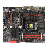
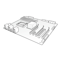
2.2.3 Layout contents
Connectors/Jumpers/Switches/Slots Page
2-35
2. ATX power connectors (24-pin EATXPWR, 8-pin EATX12V) 2-37
3. LGA1156 CPU Socket 2-8
4. DDR3 DIMM slots 2-13
5. GO Button 2-42
6. JMicron
®
JMB363 Serial ATA connectors
(7-pin SATA_ODD1 [white], SATA_ODD2 [white])
2-32
7. ROG connector (3-pin ROG) 2-33
8. Intel
®
P55 Serial ATA connectors (7-pin SATA 1-6) 2-31
9. Clear RTC RAM (3-pin CLRTC_SW) 2-26
10. System panel connector (20-8 pin PANEL) 2-38
11. JMicron
®
JMB322 Serial ATA connectors
(7-pin SPD_HDD1 [red], SPD_HDD2 [red])
2-32
2-33
13. GP connector (8-pin GP) 2-34
14. Reset switch 2-41
15. Power-on switch 2-41
16. Thermal sensor cable connectors (2-pin OPT_TEMP1–3) 2-36
16. IEEE 1394a port connector (10-1 pin IE1394_2) 2-34
Refer to 2.8 Connectors for more information about rear panel connectors and
internal connectors.
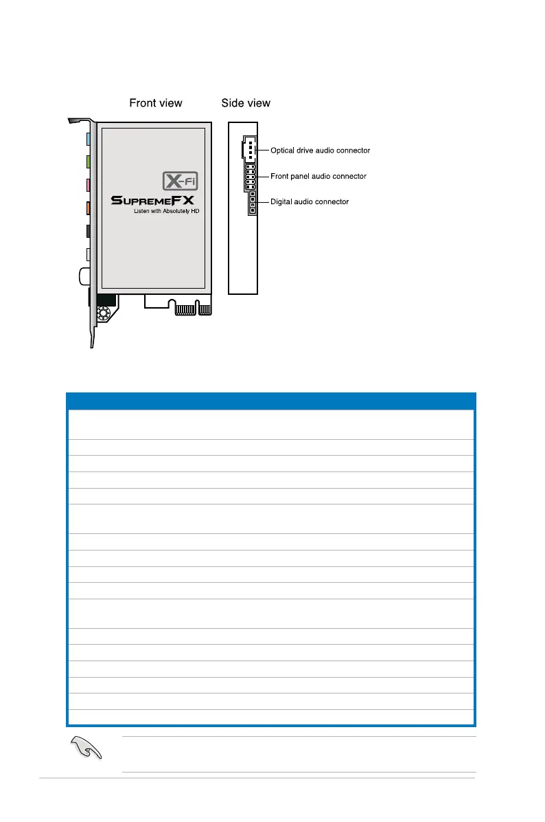
2.2.2 SupremeFX X-Fi audio card layout
2-6 Chapter 2: Hardware information
 Loading...