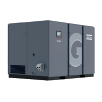
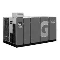
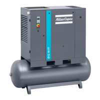
Text on figures
Reference Description
(1) Customer's installation
(2) Compressor motor
(3) Optical
Warnings
• Obey local regulations if they are stricter than the regulations mentioned in this
document.
• Obey the applicable electrical directives when installing and connecting the
compressor to the power circuit:
• CSA/UL
• UL: UL508A
• CSA: C22.2
• Do not allow voltage drops that exceed 10% of the nominal supply voltage to allow
safe shutdown of the installation within 0.4 s
• Apply the listed cable sections on main supply cables AND earth cable.
• Do not exceed the ambient temperature listed in the Limits section to avoid cable
damage.
• Mount all cables on a horizontally ventilated cable tray.
• Do not stack or group cables as this avoids heat dissipation.
• Connect the power cable with the correct (CSA certified) cable lugs on the
terminals in the electrical cabinet.
• Respect a minimum distance of 10 mm (0.4") between stripped cable ends.
• Use only the prescribed cable types:
• CSA-UL: (R, RW, T) multicore 110 °C (230 °F)
• Display the fuse type information next to the fuse holder of the mains branch.
Cable size and main fuses
Overview of fuse types
Electrical approval Fuse type
CSA/UL class RK5
1
1
Class RK5 according UL248-9
Cables, fuses and maximum cable length for Pack compressors (CSA-UL)
Model Cables Fuses (A)
Maximum
cable
length (m)
FLA*
(nominal
voltage)
(A)
FLA*
(under-
voltage)
(A)
G 160 VSD 2 x (3x MCM 600 + AWG 000) 1X (3X 500) 148 378 420
FLA*: Full-Load Ampacity
Instruction book
50 APF221384

 Loading...


