Ref. Action
4 Ventilation: the inlet grids and ventilation fan should be installed in such a way that any
recirculation of cooling air to the compressor or dryer is avoided.
The air velocity to the grids must be limited to 5 m/s (200 in/s).
The required ventilation capacity to limit the temperature of the compressor room can be
calculated from the following formula:
Q
v
= 0.92 N / ΔT
Q
v
= Required ventilation capacity in m
3
/s
N = Shaft input of compressor in kW
ΔT = Temperature increase in the compressor room in °C
5 Position of the mains cable entry.
6 The drain pipes to the drain collector must not dip into the water of the drain collector.
4.2 Dimension drawings
The dimension drawing can be found in the technical documentation supplied with the unit.
Dimension drawing Model
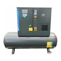
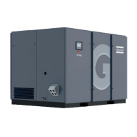
9828 0837 16 G 15L, G 18, G 22 Pack, floor-mounted
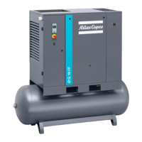
9828 0837 17 G 15L, G 18, G 22 Pack, tank-mounted
9828 0837 52 G 15L, G 18, G 22 Full-Feature, floor-mounted
9828 0837 53 G 15L, G 18, G 22 Full-Feature, tank-mounted
Text on drawings Translation or explanation
Emergency stop switch Emergency stop switch
Power supply Power supply
Cooling air and compressor inlet Cooling air and compressor inlet
Cooling air outlet of compressor and motor Cooling air outlet of compressor and motor
Service panel Service panel
Compressor controller Compressor controller
Oil level indicator Oil level indicator
Compressed air outlet (G1/2” Female) Compressed air outlet
Forklift openings Forklift openings
Valve rotation Valve rotation
Center of gravity Center of gravity
Cubicle door fully open Cubicle door fully open
Anchorpoints in base Anchorpoints in base
Air receiver safety valve Air receiver safety valve
Vessel anchor points Vessel anchor points
Air receiver manual drain (G3/8” Female) Air receiver manual drain
Dryer dewpoint indicator Dryer dewpoint indicator
Condensate drain integrated dryer Condensate drain integrated dryer
Dryer inlet cooling air Dryer inlet cooling air
Instruction book
46 2920 7119 21
 Loading...