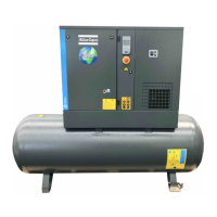
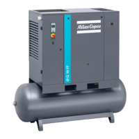
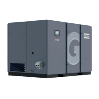
Text on drawings Translation or explanation
Dryer outlet cooling air Dryer outlet cooling air
4.3 Electrical connections
Always disconnect the power supply before working on the electrical circuit!
General instructions
Step Action
1 Install an isolating (disconnector) switch near the compressor.
2 Check the fuses and the setting of overload relay. See Settings for overload relay and
fuses.
3 If fitted, check transformers for correct connection.
4 See Electric cable size for selection of power supply line cable.
Connect the power supply cables to terminals L1, L2 and L3 (terminal block 1X0) and
the neutral conductor (if applicable) to terminal (N). Connect the earth conductor to
terminal PE/GND.
Specific voltage change instructions for G 15L – G 22 with 200 V / 230 V / 460 V cubicle
The standard voltage configuration for the compressor is mentioned on the data plate of the
machine.
When the compressors leave the factory, the units are connected for 230 V / 3 phase.
To modify the wiring for an operating voltage of 200 V or 460 V, the main cubicle should be
rewired as described below:
Instruction book
2920 7119 21 47

 Loading...


