• Underpressure from the compressor element causes loading plunger (LP) to move
downwards and inlet valve (IV) to open fully.
Air delivery is 100%, the compressor runs loaded.
Unloading
If the air consumption is less than the air output of the compressor, the net pressure increases.
When the net pressure reaches the unloading pressure, solenoid valve (Y1) is de-energised.
Results:
• The pressure above unloading valve/blow-off valve (UV) is released to atmosphere and the
space above valve (UV) is no longer in connection with the oil separator tank pressure (1).
• Unloading valve/blow-off valve (UV) moves upwards, connecting the oil separator tank
pressure (1) with channels (2) and (3).
• The pressure in channel (2) causes the loading plunger (LP) to move upwards, causing inlet
valve (IV) to close, while the pressure is gradually released to atmosphere.
• The pressure in the separator tank stabilises at low value. A small amount of air is kept
drawn in to guarantee a minimal pressure, required for lubrication during unloaded
operation.
Air output is stopped, the compressor runs unloaded.
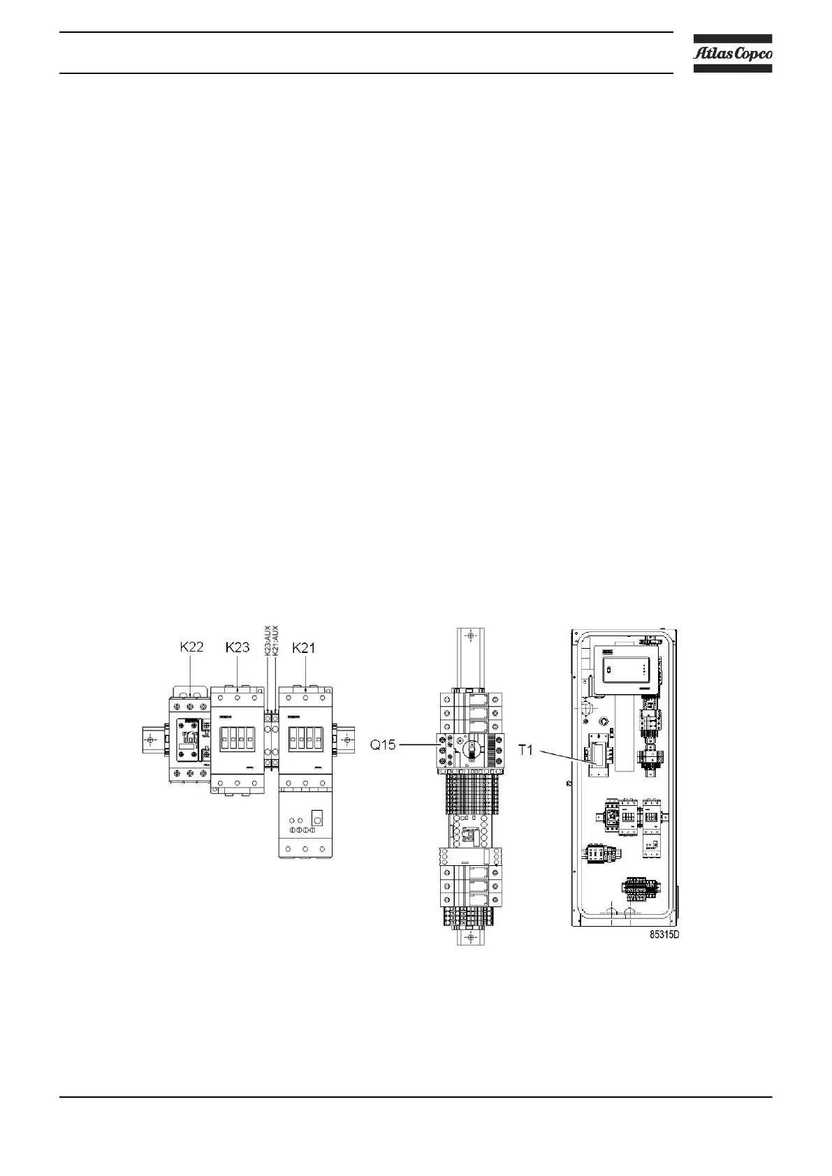
2.5 Electrical system
Electrical components
The electrical system has the following components:
Electric cabinet, typical example
Instruction book
2920 7118 31 21

 Loading...