Description
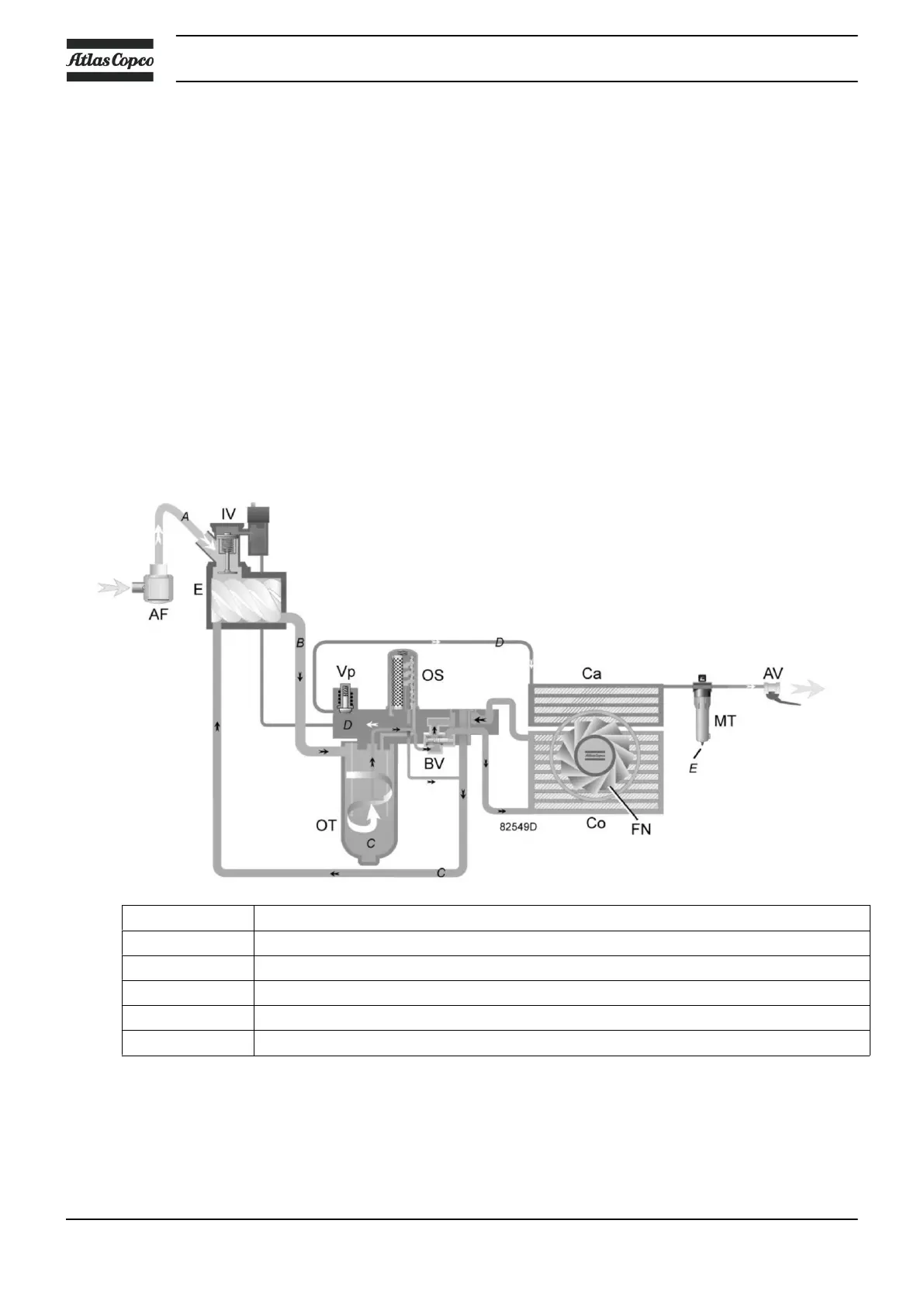
Air drawn through filter (AF) and open inlet valve (IV) into compressor element (E) is compressed.
Compressed air and oil flow into the oil tank (OT). The air is discharged through outlet valve (AV) via
minimum pressure valve (Vp) and air cooler (Ca).
During loaded operation, minimum pressure valve (Vp) keeps the pressure in the separator tank (OT) above
a minimum value, required for lubrication. An integrated check valve prevents the compressed air downstream
the valve from being vented to atmosphere during unloaded operation.
When the compressor is stopped, inlet valve (IV) closes, preventing compressed air and oil to be vented into
the air filter.
A condensate trap (MT) downstream the air cooler is included.
2.3 Oil flow
Flow diagram
Reference Description
A Intake air
B Air/oil mixture
C Oil
D Wet compressed air
E Condensate
Description
The air/oil mixture coming from the compressor element flows into the oil separator/tank, where most of the
oil is separated by centrifugal action. The oil collects in the lower part of air receiver/oil separator (OT) which
Instruction book
12 2920 7104 10
 Loading...