EasyManuals Logo

Atlas Copco GA 75 VSD User Manual

Atlas Copco GA 75 VSD
114 pages
To Next Page IconTo Next Page
To Previous Page IconTo Previous Page
Page #20 background imageLoading...
Page #20 background image
2.4 Cooling system
Flow diagrams
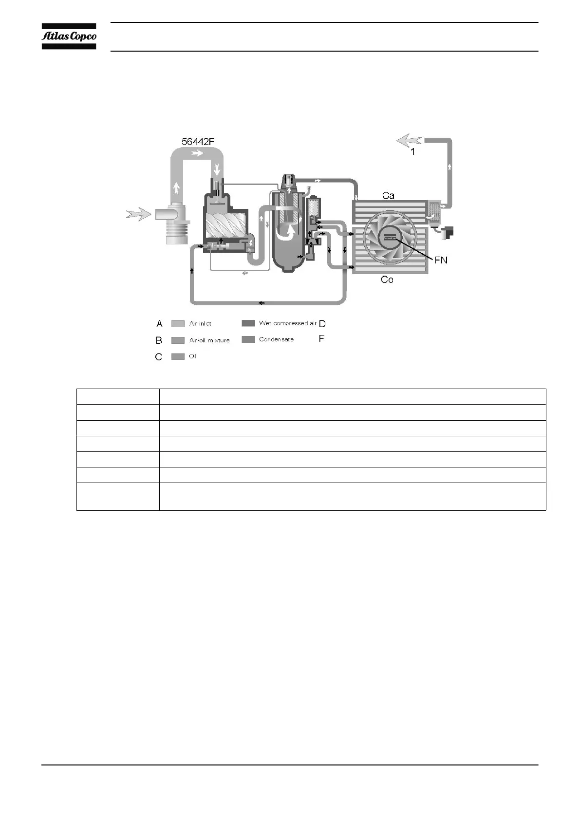
Reference Description
A Air inlet
B Air/oil mixture
C Oil
D Wet compressed air
F Condensate
1 In case of a Workplace unit to the water separator
In case of a Full-Feature unit to the dryer
Note: The cooling fan is not provided on water-cooled compressors.
Description
The cooling system comprises air cooler (Ca) and oil cooler (Co).
Air-cooled compressors have a cooling fan (FN).
Water-cooled compressors have a cooling water system. The water flows through the inlet pipe, the coolers
and the outlet pipe.
Instruction book
18 2920 1634 04

Table of Contents

Questions and Answers:

Question and Answer IconNeed help?

Do you have a question about the Atlas Copco GA 75 VSD and is the answer not in the manual?

Atlas Copco GA 75 VSD Specifications

General IconGeneral
ModelGA 75 VSD
CategoryAir Compressor
TypeRotary Screw Compressor
Power75 kW
Max Working Pressure13 bar
CoolingAir-cooled
Voltage400 V
DriveVariable Speed Drive (VSD)

Related product manuals