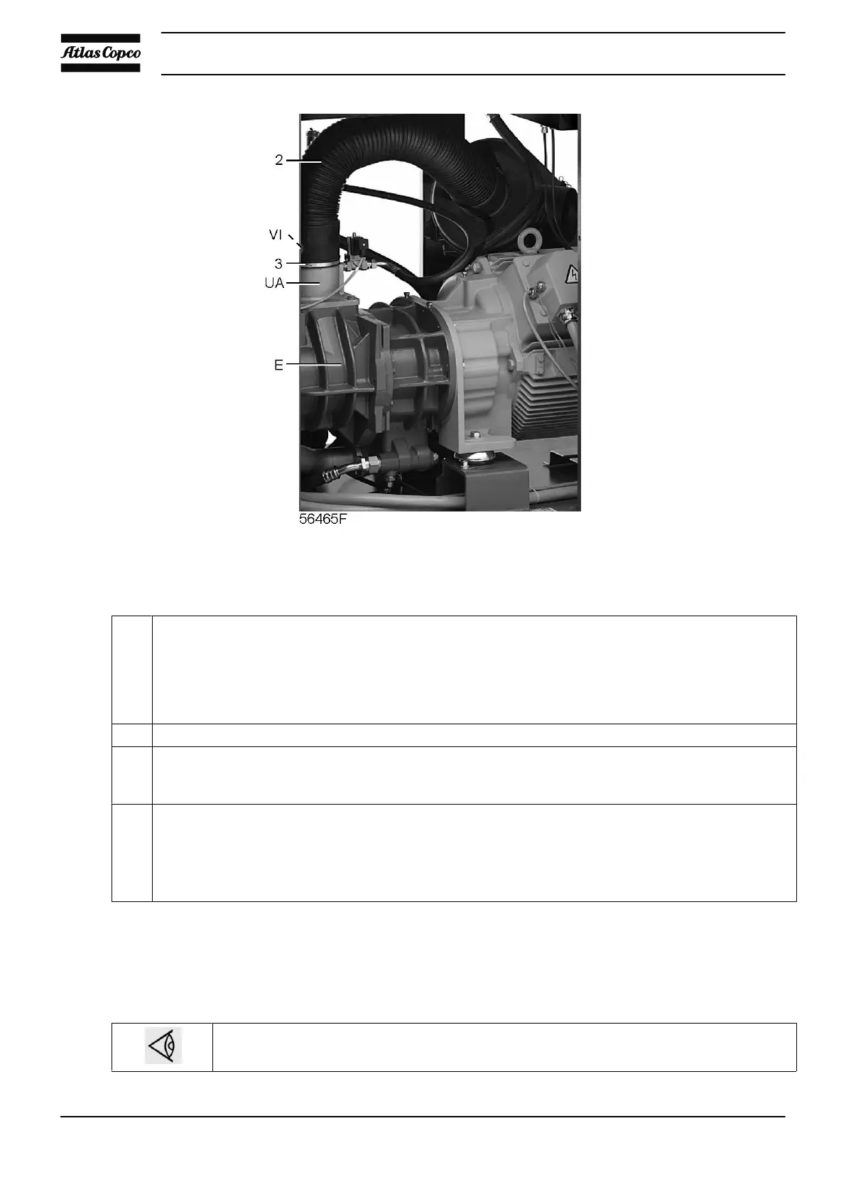
Position of unloader on GA 75 VSD and GA 90 VSD
Procedure
- See section Initial start-up for location of the oil system components.
Check oil level (Gl), top up if necessary. The pointer should be in the upper field of the green range or
in the orange range. If the pointer registers in the LOW range, depressurize the oil system (see section
Problem solving). Wait until the compressor has depressurized. Unscrew oil filler plug (FC) only one
turn to permit any pressure in the system to escape. Remove the filler cap and add oil until the level
reaches the filler neck. Tighten the plug.
- If necessary, empty the dust trap of the filter; see section Air filter.
- If the red part of the air filter service indictor shows full out, replace the air filter element. Reset service
indicator (VI) by pushing the knob in the extremity of the body and reset the service warning; see section
Service menu.
- On water-cooled compressors, also:
•
Check that the cooling water drain valves in the inlet and outlet pipes are closed.
•
Open the cooling water inlet valve.
•
Open the water flow regulating valve. This step can be overlooked if, after previous
operation, the setting of this valve has not been disturbed.
7.4 Starting
Procedure
For the position of the air outlet valve and the drain connections.
See sections Introduction and Condensate system
Instruction book
82 2920 1634 04