List of Figures
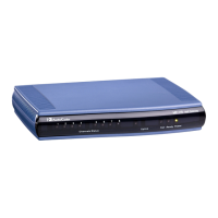
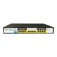
Figure 3-1: Front Panel .......................................................................................................................... 13
Figure 3-2: Rear Panel of AC-Powered MP-124 Rev. D Model ............................................................ 15
Figure 3-3: Rear Panel of DC-Powered MP-124 Rev. D Model ............................................................ 15
Figure 3-4: Rear Panel of MP-124 Rev. E Model .................................................................................. 16
Figure 4-1: Desktop Mounting ............................................................................................................... 17
Figure 4-2: Attached Brackets for Rack Installation .............................................................................. 17
Figure 5-1: MP-124 Rev. D Surge Protection and Grounding using AudioCodes FXS Patch Panel .... 21
Figure 5-2: MP-124 Rev. D Surge Protection and Grounding using Circa Directly to MDF .................. 22
Figure 5-3: MP-124 Rev. E Surge Protection and Grounding using AudioCodes FXS Patch Panel .... 24
Figure 5-4: MP-124 Rev. E Surge Protection and Grounding Connected Directly to MDF ................... 25
Figure 5-5: RJ-45 Connector Pinouts for Ethernet Interface ................................................................. 26
Figure 5-6: Connecting MP-124 to the Ethernet (e.g., Rev. E model) ................................................... 26
Figure 5-7: 50-pin Telco Connector ....................................................................................................... 27
Figure 5-8: Orderable FXS Patch Panel ................................................................................................ 28
Figure 5-9: Connecting MP-124 Rev. D to FXS Patch Panel ................................................................ 29
Figure 5-10: Connecting MP-124 Rev. E to FXS Patch Panel .............................................................. 30
Figure 5-11: Connecting Analog Equipment to FXS Patch Panel ......................................................... 31
Figure 5-12: Connecting MP-124 Rev. D Directly to MDF for FXS Cabling .......................................... 32
Figure 5-13: Connecting MP-124 Rev. E Directly to MDF for FXS Cabling .......................................... 33
Figure 5-14: 50-Pin Telco Cable Secured to Device's Connector using Orderable Velcro Strap ......... 34
Figure 5-15: Removing Bail Locks from Telco Connector ..................................................................... 34
Figure 5-16: Attaching Bracket over Telco Connector (e.g., Short Screws) .......................................... 35
Figure 5-17: Feeding Velcro Strap through Bracket Slots ..................................................................... 35
Figure 5-18: Sliding Cable through Velcro Strap ................................................................................... 35
Figure 5-19: Attaching Cable Connector to Device's Telco Connector ................................................. 35
Figure 5-20: Pulling Velcro Strap to Reduce Slack over Cable ............................................................. 36
Figure 5-21: Feeding Velcro Strap through Strap Buckle ...................................................................... 36
Figure 5-22: Attaching Velcro Strap to Itself .......................................................................................... 36
Figure 5-20: Mini Patch Panel for FXS Interfaces ................................................................................. 37
Figure 5-20: Connecting FXS Lines using Mini Patch Panel ................................................................. 38
Figure 5-23: DB-9 Connector Pinouts for Serial Interface ..................................................................... 39
Figure 5-24: Connecting MP-124 Rev. D for Serial Communication ..................................................... 39
Figure 5-25: RJ-45 to DB-9 Serial Cable Adapter ................................................................................. 40
Figure 5-26: Connecting MP-124 Rev. E for Serial Communication ..................................................... 40
Figure 5-27: Connecting MP-124 to AC Power Supply (e.g., Rev. E model) ........................................ 42
Figure 5-28: DC Terminal Block ............................................................................................................ 43
Figure 5-29: Wired DC Power Terminal Block Connected to MP-124 Rev. D ...................................... 43
List of Tables
Table 1-1: MP-124 Models and Support .................................................................................................. 9
Table 3-1: Physical Dimensions and Operating Environment ............................................................... 13
Table 3-2: Front-Panel LED Description ................................................................................................ 14
Table 3-3: MP-124 Rev. D Rear-Panel Description ............................................................................... 15
Table 3-4: MP-124 Rev. E Rear-Panel Description .............................................................................. 16
Table 3-5: Rear-Panel Ethernet LEDs Description ................................................................................ 16
Table 5-1: 50-pin Telco Connector Pinouts ........................................................................................... 27
Table 5-2: RJ-45 to DB-9 Serial Cable Connector Pinouts ................................................................... 40
Table 5-3: Power Specifications ............................................................................................................ 41
 Loading...
