MediaPack Analog Gateways 41 MP-124
Hardware Installation Manual 5. Cabling the Device
2. Connect the DB-9 connector, at the other end of the cable adapter, to either the COM
RS-232 communication port on your computer.
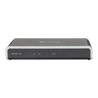
Once you power-up the device, the Ready and LAN LEDs on the front panel light up green
(after a self-testing period of about a minute). Any malfunction in the startup procedure
changes the Ready LED to red.
5.5 Connecting to Power
The device can be powered from either a standard AC electrical outlet or a 48-VDC power
supply, depending on MP-124 model:
MP-124 Rev. E: AC only
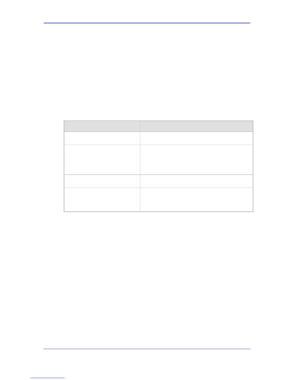
Table 5-3: Power Specifications
Physical Specification Description
Power Supply
Single universal power supply
Input Ratings
MP-124 Rev. D:
AC: 100-240 VAC, 50-60 Hz, 0.8A max
DC: -48V DC
MP-124 Rev. E:
AC: 100-240 VAC, 50-60 Hz, 1A max
Output Ratings
204.7 BTU/hr
Max. Power Consumption
MP-124 Rev. D: 73W
MP-124 Rev. E:
46W: 24 ports @ off-hook long haul
65W: 24 ports @ continuous REN2 ringing
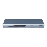
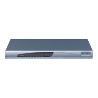
After powering-up the device, the Ready and Power LEDs on the front panel light up green
(after a self-testing period of about two minutes). Any malfunction in the startup procedure
changes the Fail LED to red and the Ready LED is turned off.
 Loading...