Chapter 6: Installation reference
Console and management connections
The front panel of the switch contains the Status LEDs, Console port, and a USB 2.1 port.
The rear panel of the switch contains the Base Unit switch.
Console port
The console port is the RJ45 port with a blue border outline. You can use the console port to
establish a management terminal connection to the switch. You can use an RJ45 to DB-9 cable, or
a DB-9 to RJ45 adapter to connect the switch console port to your management terminal. The
maximum length of a console cable is 25 feet (8.3 meters).
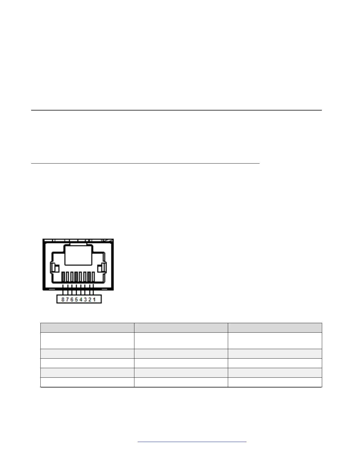
The following figure and table describe the RJ45 console port pin-out information. You can use the
pin-out information to verify or create a console cable for use with your maintenance terminal.
Figure 7: RJ45 console port pin-out
RJ45 console port pin-out Signal Requirement
1 RTS (ready to send) Optional (can be swapped or
linked with pin
2 DTR (data terminal ready) Optional
3 TXD (transmit data) Mandatory
4 DCD (carrier detect) Optional
5 GND (ground) Mandatory
Table continues…
January 2017 Installing Avaya Ethernet Routing Switch 3600 Series 35
Comments on this document? infodev@avaya.com
 Loading...