Mounting and wiring
Wire cross section 0,5 ... 2.5 mm
2
AWG 20 … AWG 14
Strip length 8 ... 9 mm 8.38 mm
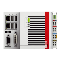
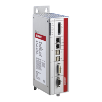
LED
If the power supply unit is connected correctly and the power supply is switched on, the two upper LEDs in
the terminal prism are green. The left LED (Us) indicates the CPU supply. The right LED (Up) indicates the
terminal supply. The other LEDs indicate the Terminal Bus status. A detailed description of the LEDs can be
found in section “LED troubleshooting”.
UL requirements
DANGER
Compliance of the UL requirements
For the compliance of the UL requirements the CX-Controllers should only be supplied by a
24 VDC supply voltage, supplied by an isolating source and protected by means of a fuse
(in accordance with UL248), rated maximum 4 Amp.by a 24 VDC power source, that has to
satisfy NEC class 2. A NEC class 2 power supply shall not be connected in series or paral-
lel with another (class 2) power source!This UL requirements are valid for all supply volt-
ages of the CX-Controllers!
DANGER
Compliance of the UL requirements
To meet the UL requirements, the CX-Controllers must not be connected to unlimited
power sources!
PE power contacts
Attention
Power contact “PE”
The “PE” power contact must not be used for other potentials. “PE" and “0V" (24 V system
supply) must have the same potential (connected in the control cabinet). The cabling in the
control cabinet must comply with EN 60204-1:2006 PELV - Protective Extra-Low Voltage.
EN 60204-1:2006 section 6.4.1:b): One side of the circuit or one point of the energy source
for this circuit must be connected the protective earth conductor system.
Attention
Interruption of the power supply / switching off
The device may not be switched off by disconnecting the ground. The 24 V line must al-
ways be disconnected first, since otherwise current may continue to flow via the shielding,
depending on the device. Any devices with independent power supply that may be con-
nected (e.g. a Panel) must have the same potential as the CX system for “PE" and
“GND" (no potential difference). A potential difference may result in damage to the con-
troller and the periphery.
CX51x036 Version: 1.6
 Loading...