2.4.2 Connection of the motor
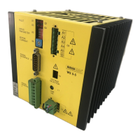
1. Prepare the 5 wires of the motor cable and the
screen which are to be connected to the plug
end with boot lace ferrules.
2. Insert the 6 wires into cap of the mating plug as
shown in Figure 2-4 and tighten the screws.
3. Join the two plug shell halves together.
4. Set the plug to connection 09 and tighten screws.
CAUTION
•
To minimise the losses in the cable
and the power drive, it is advisable
to have as short a cable route as
possible.
•
The maximum length of the motor
cable is 50 m.
•
For cable diameter, see technical
data.
DANGER
The locking mechanism of the motor
plug may only be opened when the
mains voltage has been disconnected.
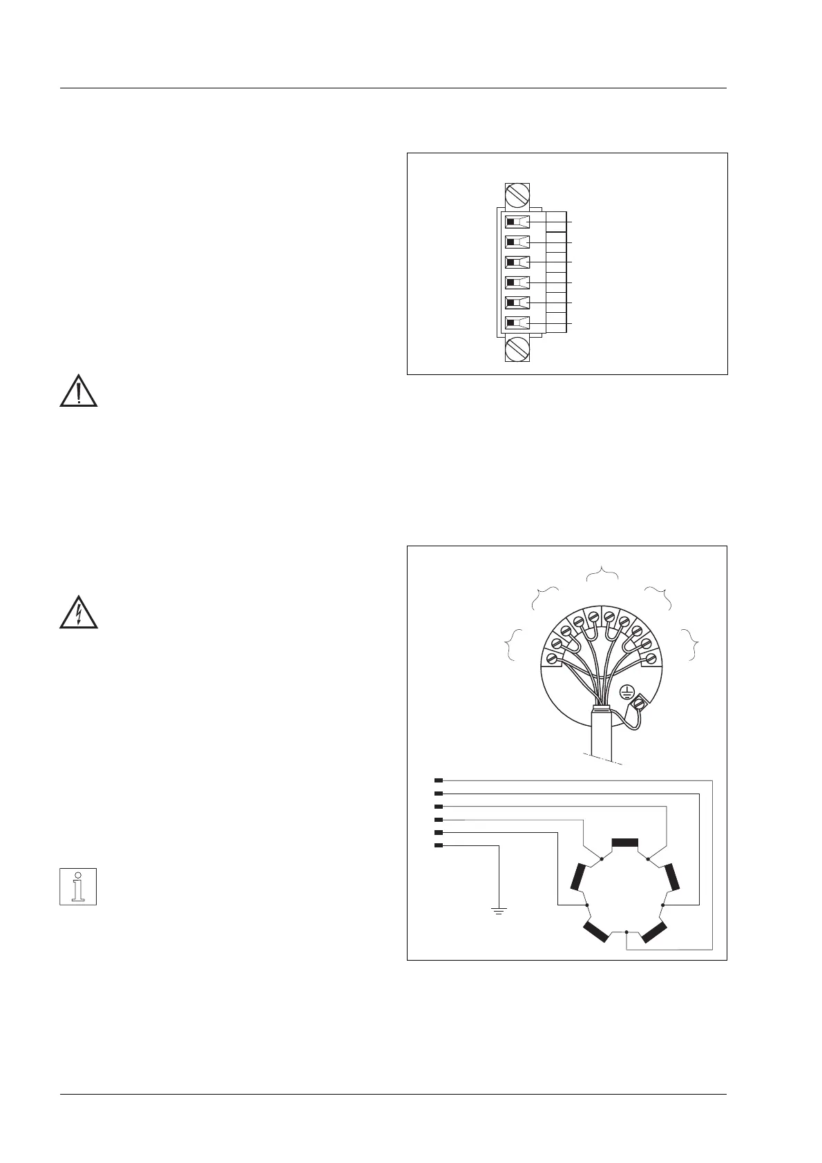
Circuitry of the motor
The circuitry of the motor uses a pentagram connec-
tion, see Figure 2-5.
NOTE
In the pentagram circuit twice the
phase current flows in the motor con-
necting wires.
A1
A2
A3
A4
A5
A6
Phase1
Phase2
Phase3
Phase4
Phase5
Screen(PE)
yellow
blue
orange
grey
brown
09
Figure 2-4 Motor connection
W4
W4
W5
W5
W1
W1
W3
W3
W2
W2
5
4
3
2
1
6
BN
GY
OG
BU
YE
BU
BU
RD
RD
OG
OG
GN
GN
GY
GY
BK
BK
BN
BN
VI
VI
YE
YE
WH
WH
.
.
.
.
.
WH
YE
VI
BN
BK
GY
GN
OG
RD
BU
=
=
=
=
=
=
=
=
=
=
white
yellow
violet
brown
black
grey
green
orange
red
blue
0
3
2
1
4
5
6
7
8
9
Figure 2-5 Circuitry of the motor
Installation
2 – 4 WS5-5 Doc. no. 211.347/DGB 03.96
 Loading...