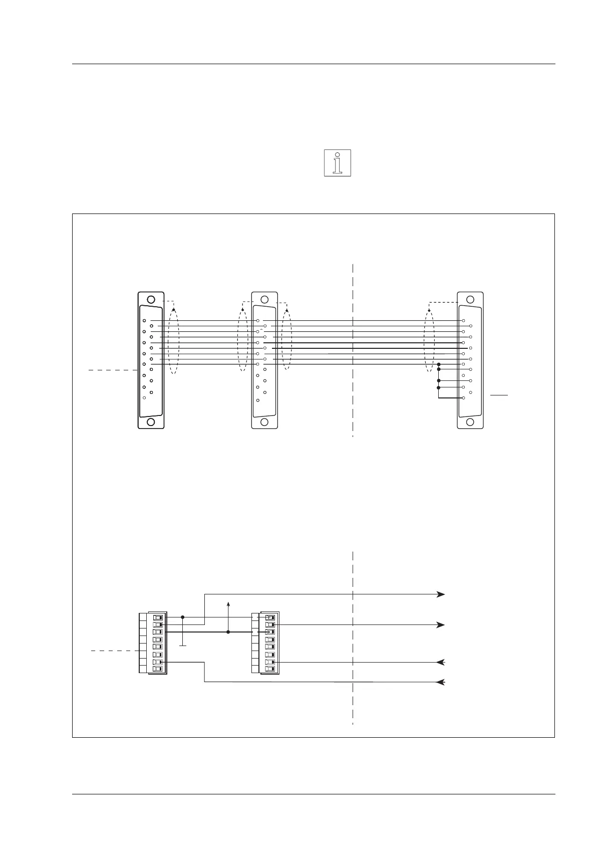
2.4.7.3 Driving of two WS5-5 via WP111
positioning unit from BERGER
If two WS5-5 power drives are driven via a position-
ing unit WP111, the WS5-5 are to be connected in
parallel.
NOTE
Resistance to interference of data
transfer is reduced, if a cable without
screening is used to drive the WS5-5.
8
7
6
5
4
3
2
1
2
3
4
5
6
7
8
1
9
10
11
12
13
14
15
*
WS5-5
2
3
4
5
6
7
1
9
10
11
12
13
14
15
2
3
4
5
6
7
8
1
9
10
11
12
13
14
15
2
3
4
5
6
7
1
9
10
11
12
13
14
15
*
2
3
4
5
6
7
1
9
10
11
12
13
14
15
2
3
4
5
6
7
1
9
10
11
12
13
14
15
*
2
3
4
5
6
7
1
9
10
11
12
13
14
15
2
3
4
5
6
7
8
1
9
10
11
12
13
14
15
6
7
8
13
14
15
8
7
6
5
4
3
2
1
WS5-5
+24 V
+24 V GND
1
9
2
3
4
5
10
11
12
GND
- READY
+READY
- ZERO PHASE
+ZERO PHASE
PWM/BOOST
GATE
ENABLE
OutputsInputs
+PULSE
- PULSE
+DIRECTION
- DIRECTION
+ENABLE
- ENABLE
+PWM/BOOST
- PWM/BOOST
GND
+READY
- READY
InputsOutputs
GND
READY
*
Sub-D-socket
OPEN COLLECTOR-output (npn)
I
max
= 10 mA
U
CEsat
≤ 1,2 V (short-circuit-proof up to 6 V)
Positioning unit WP111
Interface 1
Interface 2
Sub-D-socket
+PULSE
- PULSE
+DIRECT.
- DIRECT.
+ENABLE
- ENABLE
+IPWMIN
- IPWMIN
GND
RM FAULT
TEMP. INT.
TEMP. MOT.
GND
READY
Sub-D-socket
+24 V: READY signal
(PLC input)
Superior SPC
WS5-5 (axis 2)WS5-5 (axis 1)
+24 V: pulses are blocking
(PLC input)
+24 V: pulses are blocking
(PLC input)
+24 V: READY signal
(PLC input)
Figure 2-15 Driving of two WS5-5 via WP111
Installation
WS5-5 Doc. no. 211.347/DGB 03.96 2 – 11
 Loading...