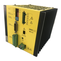
1 General Description 1-1
1.1 Construction and characteristics 1-1
1.2 Application/system integration 1-2
1.3 Function 1-3
1.4 Technical data 1-4
1.4.1 Electrical data 1-4
1.4.1.1 Mains connection 1-4
1.4.1.2 Motor connection 1-4
1.4.1.3 Signal connection of signal interface 1 1-4
1.4.1.4 Signal connection of signal interface 2 1-4
1.4.1.5 Equipment protection 1-4
1.4.2 Mechanical data 1-5
1.4.3 Ambient conditions 1-6
2 Installation 2-1
2.1 Parts specification 2-1
2.2 Accessories 2-2
2.3 Mounting 2-3
2.4 Cabling 2-3
2.4.1 General instructions 2-3
2.4.2 Connection of the motor 2-4
2.4.3 Adjustment of the equipment to mains voltage 2-5
2.4.4 Connecting of the mains cable 2-5
2.4.5 Connection of the signal cables 2-6
2.4.6 Wiring of the signal interfaces 2-7
2.4.7 Examples for application 2-9
2.4.7.1 Basic driving possibilities 2-9
2.4.7.2 Driving the WS5-5 via positioning unit from BERGER (WP111, WP311) 2-10
2.4.7.3 Driving of two WS5-5 via WP111 positioning unit from BERGER 2-11
2.4.7.4 Driving of two WS5-5 via WP311 positioning unit from BERGER 2-12
2.4.7.5 Driving via PLC IP267 from Siemens 2-13
2.4.7.6 Driving via PLC IP247 from Siemens 2-13
2.5 Initial operation 2-14
2.5.1 Checklist for initial operation 2-14
2.5.2 Basic settings 2-14
3 Operation 3-1
3.1 Signal description 3-1
3.1.1 Input signals 3-1
3.1.2 Output signals 3-3
3.2 Switching on 3-4
3.3 Operating facilities 3-4
3.4 Switching off 3-4
Table of Contents
WS5-5 Doc. no. 211.347/DGB 12.92

 Loading...