3.1.2 Output signals
NOTE
’Active’ output means low-impedance.
’Inactive’ output means high-imped-
ance.
READY
When the output is ’active’, the power stage of the
WS5-5 is operative (see Figure 3-2).
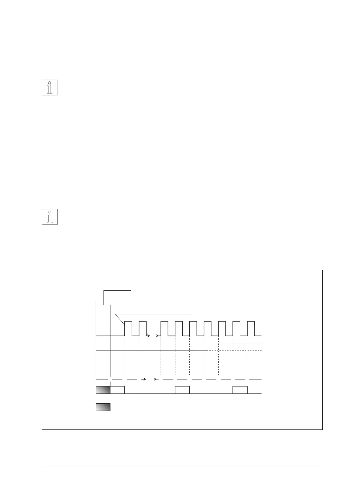
0-PHASE (ring counter reading zero)
Each time the ring counter reading is zero, this out-
put is switched to ’active’ (low impedance)
(see Figure 3-4).
NOTE
Figure 3-4 shows how the 0-PHASE
output signal depends on the ring
counter reading in the case of full-step
operation. With half-step operation the
ring counter has a cycle of 20 steps.
PULSE
DIRECTION
Ring counter
0-PHASE
active
active
inactive
inactive
low-impedance
high-impedance
no defined range
12 901210
9
....
....
2 9 10 11 12 13 14 151
active edge
Power on
ENABLE
0
Figure 3-4 Dependence of the 0-PHASE output on the ring counter
Operation
WS5-5 Doc no. 211.347/DGB 12.92 3 – 3