2.5 Initial Operation
2.5.1 Checklist for initial operation
Before you start to make the basic settings to the
equipment, check the following points:
• Has the equipment been correctly installed and
fitted (see section 2.3)?
• Is there a reliable ventilation flow to and from the
equipment?
• Is the equipment correctly wired and cabled (see
section 2.4)?
• Has the equipment been adjusted for the exist-
ing mains voltage?
• Have motor and signal cables been laid with a
good space between them?
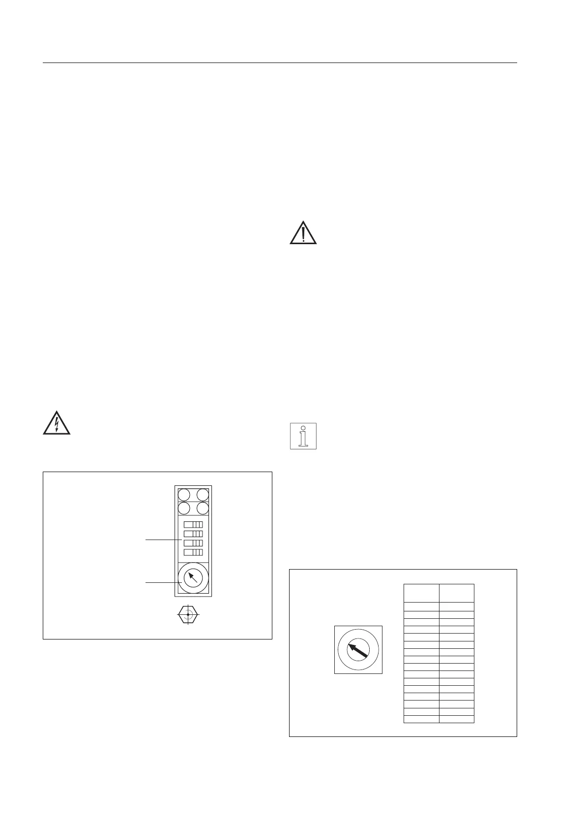
2.5.2 Basic settings
The basic settings are made using the current selec-
tor and parameter switch (Figure 2-19) as follows:
DANGER
Disconnect the equipment before start-
ing to make any adjustments!
Setting of the phase current
Setting the phase current using rotary switch 06.
For the possible settings, see Figure 2-20. If it is
found to be impossible to set the phase current indi-
cated on the rating plate of the motor, set the next
lowest value.
CAUTION
• Never set too high a current! The
maximum phase current must not be
exceeded and, if it is, this must be
only momentarily (boost signal). This
is to prevent overloading of the
motor. Make sure the motor is adequ-
ately cooled (temperature on motor
housing must not exceed 100°C)!
• The phase current must be set to
max. 2.65 A for the motors ExRDM
5913/50P and ExRDM 599/50P!
Current increase via Boost is not per-
mitted.
NOTES
• Smaller phase currents are per-
missible, but of course the torque is
correspondingly reduced.
• To reduce power dissipation, the
automatic current reduction system
should be switched on when the
system is at rest (see Figure 2-21).
Parameter
switch
Current
selector
switch
01
03
02
04
05
06
Figure 2-19 Setting elements
Switch
position
Phase
current[A]
0
1
2
3
4
5
6
7
8
9
A
B
C
D
E
F
0,55
0,70
0,85
1,00
1,15
1,30
1,45
1,60
1,75
1,90
2,05
2,20
2,35
2,50
2,65
2,80
0
1
2
3
4
5
6
7
8
9
A
B
C
D
E
F
Switchforthe
phasecurrent
06
Figure 2-20 Settings of the phase current
Installation
2 – 14 WS5-5 Doc. no. 211.347/DGB 03.96