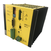
EasyManuals Logo
Home>Berger Lahr>DC Drives>WS5-5 Series

Berger Lahr WS5-5 Series User Manual

Berger Lahr WS5-5 Series
45 pages
To Next Page IconTo Next Page
To Previous Page IconTo Previous Page
Page #20 background imageLoading...
Page #20 background image
Signal interface 2
The input level of signal interface 2 corresponds to
the PLC standard. The drive may be provided by
any commercial PLC.
NOTE
The outputs +READY (pin 6) and
-READY (pin 14) of signal interface 1
are connected in parallel to +READY
(pin 6) and -READY (pin 7) of inter-
face 2.
+
U
S
+
U
33 V
2 k
1, 2, 3
4, 6
5, 7
8
U
S low
= 0 V to 3 V
U
S high
= 13 V to 0 V
R
i
4,7 k
I
L
= 0,4 mA to 25 mA
Inputs
Outputs
Figure 2-12 Internal wiring of signal interface 2
Installation
2 – 8 WS5-5 Doc. no. 211.347/DGB 03.96

Questions and Answers:

Question and Answer IconNeed help?

Do you have a question about the Berger Lahr WS5-5 Series and is the answer not in the manual?

Berger Lahr WS5-5 Series Specifications

General IconGeneral
BrandBerger Lahr
ModelWS5-5 Series
CategoryDC Drives
LanguageEnglish