5
HTE402559 25/47
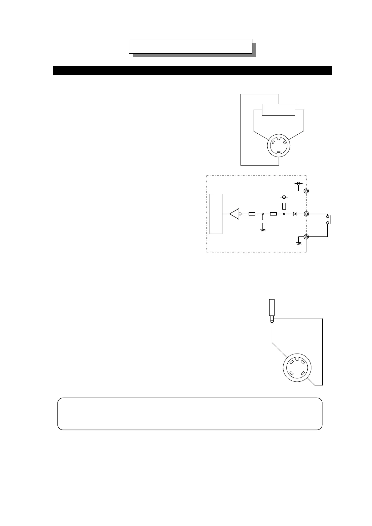
Connection of Overflow Connector “Work Sensor”
a. VMC-controller provides power supply,
DC 12V and maximum 80 mA, to the Overflow sensor
with a plug and socket connector, three cored, on it.
b. Dry contacts or Open Collector,
maximum sink current 10 mA, is connected
to the No.2 and No. 3 core of
the plug connector controls VMC-controller.
When No.2 and No.3 core is closed
the partsfeeder stops. When No.2 and No.3 core
is open the partsfeeder runs.
No.2 and No.3 core is open: On Delay setting
No.2 and No.3 core is closed: Off Delay setting
Note: A proximity switch powered by DC with
two cores can not be used.
Connection of Stroke sensor “PF/LF Sensor”
Connection diagram is shown on the right side.
Note: The maximum wiring cable length should be 10m.
When the cable is longer than 10m a shield cable
with an excellent high-frequency characteristic must be used.
+12V 0V
SENSOR
1 3
2
OUT
Caution: On the soldering of the cable on the cores of a plug connector,
do not mistake the shield for the core nor the core for the shield.
(No.2) Input
Inner Circuit
(No.1)+12V
(No.3) 0V
+12V
470Ω
+5V
1
2
Shield
Core lead
Dry contacts or Open Collector
Open:Run
Close:Stop
Connection of Overflow and S
-Continued-
 Loading...