5
HTE402559 30/47
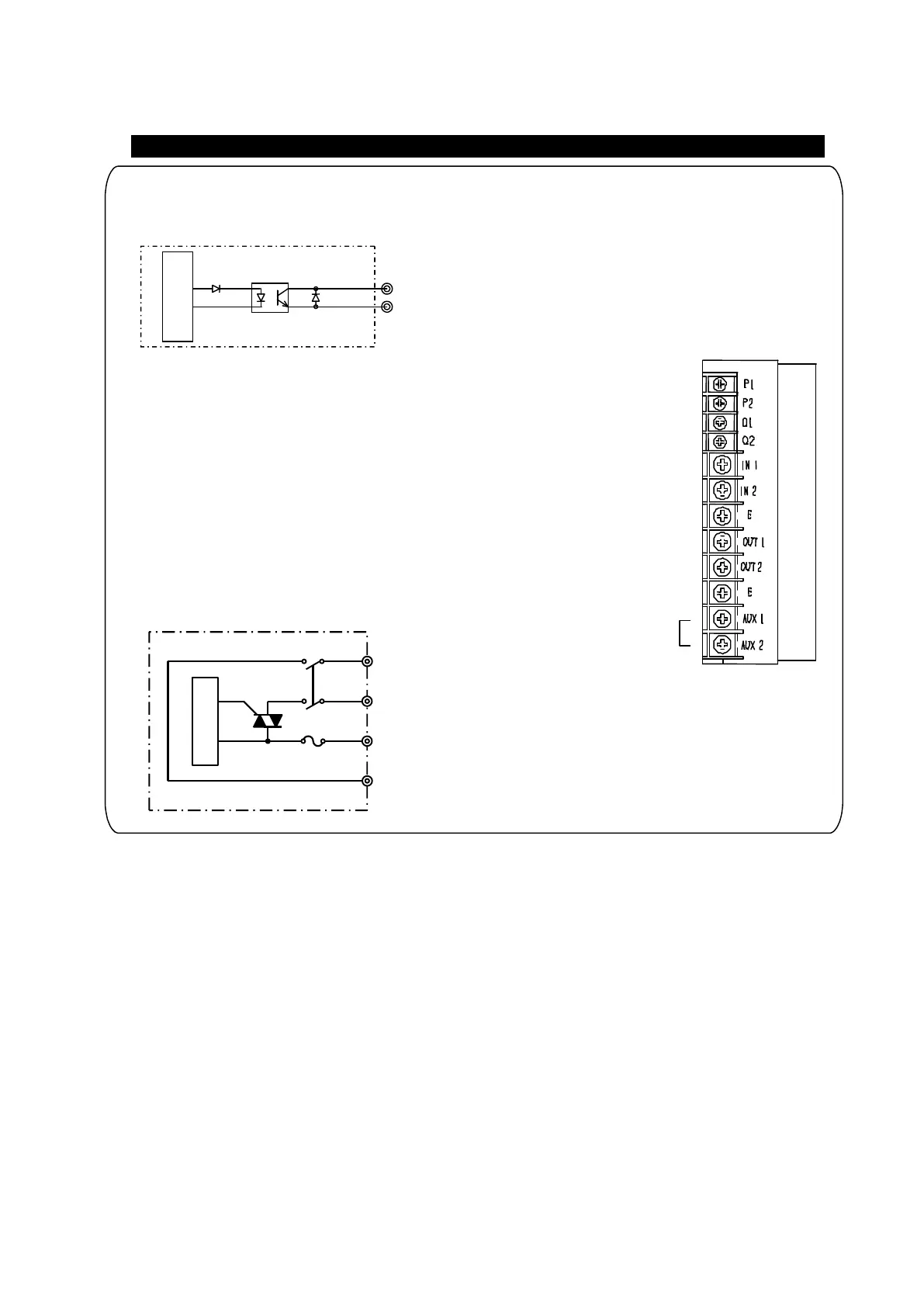
Inner Circuit
AUX1
AUX2
IN1
IN2
Power Switch
Operation Synchronous Signal Terminals Q1 and Q2
The terminal Q1 and Q2 outputs the synchronous signal with
running and stopping of the partsfeeder.
The output transistor closes when
a partsfeeder is running.
Maximum output voltage: DC 24 V
Maximum output current: 80 mA
LED「RUN」
Q1
Q2
Operation Synchronous power output terminals AUX. OUT
The terminals, AUX1 and AUX2, output power supply synchronous
with operation of the partsfeeder.
Output voltage: The same as the input voltage to
VMC-controller
Maximum current: 2A
Leak current at stop condition : 2mA
Operation Synchronous Signal Terminals Q1 and Q2, and AUX. OUT
AUX OUT(2A)
Inner Circuit
 Loading...