5
HTE402559 6/47
① Remove the control panel
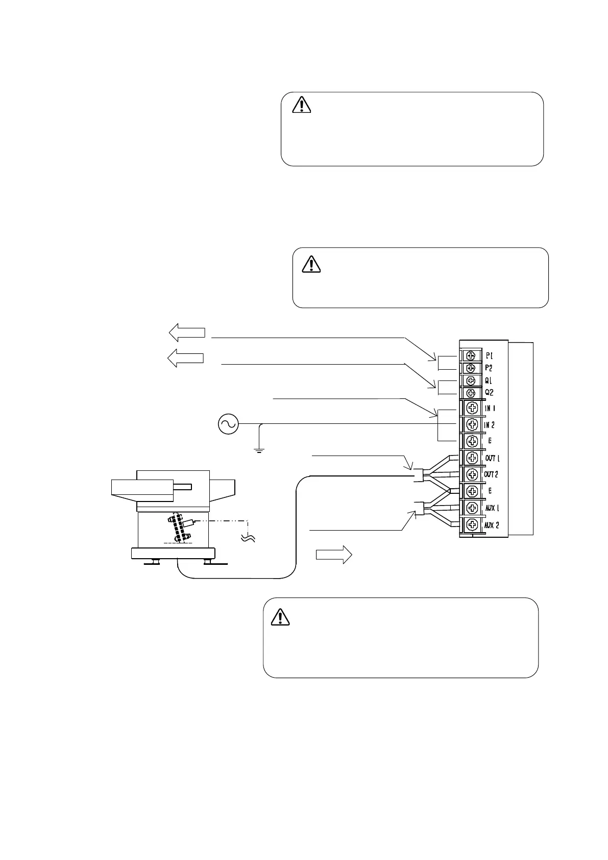
② Connect power supply cable and the output cable for load. Connect the stroke sensor.
Wire each cable or lead on the terminals through rubber bushings respectively.
Power supply cable to terminals “IN1”, “IN2” and “E”
Output cable to terminals “OUT1”, “OUT2” and “E”
③ Close the control panel
The control panel must be closed and secured
while VMC-controller is in operation. Or else
the operator should get an electric shock.
Danger:
Before remove the control panel,
disconnect and lock out the power supply at
the safety disconnect switch.
Connect the ground line to terminal “E”
without fail
Warning
Danger:
Note: If any noise from the controller disturbs any other device, the controller
should provide suitable noise suppression parts on it at your own expense.
Please consult “Conformity with CE Marking” on page 37 for selection and
installation of the parts.
Ground Line
Stroke Sensor
Operation Output Signal Terminals
Output Terminals
External Operation Signal Terminals
See page 30
See page 29
Synchronous power
output terminals
See page 30
Power supply Terminals
 Loading...