Contents | 11
6 720 819 669 (2016/05)MC 400
Contents
1 Key to symbols and safety instructions . . . . . . . . . . . . . . . . . 11
1.1 Key to symbols . . . . . . . . . . . . . . . . . . . . . . . . . . . . . . . . 11
1.2 General safety instructions . . . . . . . . . . . . . . . . . . . . . . 11
2 Product details . . . . . . . . . . . . . . . . . . . . . . . . . . . . . . . . . . . . . . 12
2.1 Important usage information . . . . . . . . . . . . . . . . . . . . 12
2.2 Function description . . . . . . . . . . . . . . . . . . . . . . . . . . . 12
2.2.1 Basic principle . . . . . . . . . . . . . . . . . . . . . . . . . . . . . . . . 12
2.2.2 Time limits . . . . . . . . . . . . . . . . . . . . . . . . . . . . . . . . . . . 12
2.3 Control strategies . . . . . . . . . . . . . . . . . . . . . . . . . . . . . 13
2.3.1 Serial standard cascade . . . . . . . . . . . . . . . . . . . . . . . . 13
2.3.2 Serial optimised cascade . . . . . . . . . . . . . . . . . . . . . . . 13
2.3.3 Serial cascade with peak load coverage . . . . . . . . . . . . 13
2.3.4 Parallel cascade . . . . . . . . . . . . . . . . . . . . . . . . . . . . . . . 13
2.3.5 Output control . . . . . . . . . . . . . . . . . . . . . . . . . . . . . . . . 13
2.3.6 Flow temperature control . . . . . . . . . . . . . . . . . . . . . . . 13
2.3.7 Pump pre-run . . . . . . . . . . . . . . . . . . . . . . . . . . . . . . . . . 13
2.4 Setting the coding card . . . . . . . . . . . . . . . . . . . . . . . . . 14
2.5 Scope of delivery . . . . . . . . . . . . . . . . . . . . . . . . . . . . . . 14
2.6 Specifications . . . . . . . . . . . . . . . . . . . . . . . . . . . . . . . . 14
2.7 Additional accessories . . . . . . . . . . . . . . . . . . . . . . . . . 14
2.8 Cleaning . . . . . . . . . . . . . . . . . . . . . . . . . . . . . . . . . . . . . 14
3 Mounting . . . . . . . . . . . . . . . . . . . . . . . . . . . . . . . . . . . . . . . . . . . 14
3.1 Installation . . . . . . . . . . . . . . . . . . . . . . . . . . . . . . . . . . . 14
3.2 Installation of temperature sensor on the low loss
header . . . . . . . . . . . . . . . . . . . . . . . . . . . . . . . . . . . . . . .15
3.3 Electrical connection . . . . . . . . . . . . . . . . . . . . . . . . . . . 15
3.3.1 Connecting the BUS connection and temperature
sensor (extra-low voltage side) . . . . . . . . . . . . . . . . . . .15
3.3.2 Connecting the power supply, pump and mixer
(mains voltage side) . . . . . . . . . . . . . . . . . . . . . . . . . . . .15
3.3.3 Connection diagrams with system schematics . . . . . . 16
3.3.4 Overview of the terminal assignment . . . . . . . . . . . . . . 16
4 Commissioning . . . . . . . . . . . . . . . . . . . . . . . . . . . . . . . . . . . . . . 17
4.1 Setting the coding card . . . . . . . . . . . . . . . . . . . . . . . . . 17
4.2 System and module commissioning . . . . . . . . . . . . . . . 17
4.2.1 Settings for systems with a cascade module in
the BUS system . . . . . . . . . . . . . . . . . . . . . . . . . . . . . . . .17
4.2.2 Settings for systems with 2 or more cascade
modules in the BUS system . . . . . . . . . . . . . . . . . . . . . .17
4.3 Status display for the heat source/subordinate
cascade modules on the subordinate cascade modul
e . .17
4.4 Status display for the heat source on the
subordinate cascade module . . . . . . . . . . . . . . . . . . . . .17
4.5 Cascade settings menu . . . . . . . . . . . . . . . . . . . . . . . . . 18
4.6 Diagnosis menu . . . . . . . . . . . . . . . . . . . . . . . . . . . . . . . 18
5 Eliminate fault . . . . . . . . . . . . . . . . . . . . . . . . . . . . . . . . . . . . . . 19
5.1 Status indicator on the individual installed or
higher-level cascade module . . . . . . . . . . . . . . . . . . . . .19
5.2 Status indicator on the lower-level cascade module . . 19
6 Environment / disposal . . . . . . . . . . . . . . . . . . . . . . . . . . . . . . . 19
1 Key to symbols and safety instructions
1.1 Key to symbols
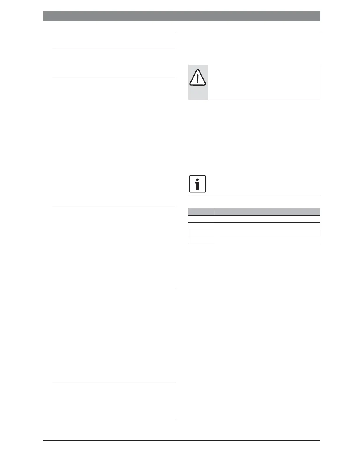
Warnings
The following keywords are defined and can be used in this document:
• NOTICE indicates a situation that could result in damage to property
or equipment.
• CAUTION indicates a situation that could result in minor to medium
injury.
• WARNING indicates a situation that could result in severe injury or
death.
• DANGER indicates a situation that will result in severe injury or
death.
Important information
Additional symbols
1.2 General safety instructions
These installation instructions are intended for a competent person.
▶ Read the installation instructions (heat appliances, modules, etc.)
before installation.
▶ Observe safety instructions and warnings.
▶ Observe national and regional regulations, technical rules and
guidelines.
▶ Keep a record of any work carried out.
Determined use
▶ Use the product only to control heating systems with cascade
systems. In a cascade system, several heat sources are used to
achieve greater heat output.
Any other use is considered inappropriate. Any damage that may result
is excluded from liability.
Installation, commissioning and maintenance
Installation, commissioning and maintenance must only be carried out
by a competent person.
▶ Never install the product in wet rooms.
▶ Only install genuine spare parts.
Warnings in this document are identified by a warning
triangle printed against a grey background.
Keywords at the start of a warning indicate the type and
seriousness of the ensuing risk if measures to prevent
the risk are not taken.
This symbol indicates important information where
there is no risk to people or property.
Symbol Explanation
▶ Step in an action sequence
Æ Cross-reference to another part of the document
• List entry
– List entry (second level)
Table 1
 Loading...