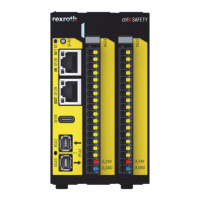
12.2 Status display
A status display on the front panel of the control is used for error diagnostics.
The following functions are assigned to the status display when the system firmware is running:
Table 14: Status display
State Color Function
Init Flashing blue The application is started and initialized, “Init” state
Stop Blue The application is in “Stop” state
Run Green The application is in “Run” state
Error Flashing red The application is in “Error” state
System error Red The application is in “SysError” state
Shutdown Flashing blue The application is in “Shutdown” state
12.3
Initial firmware
Upon delivery, the ctrlX CORE is provided with the operating system (Linux) including all system-rele-
vant apps and optionally selected apps. The operating system provides commissioning and mainte-
nance functions.
12.4
Booting
The ctrlX CORE control starts booting after switching on the 24 V voltage supply. Booting can be moni-
tored and checked using the status display.
The following boot sequence is defined:
eMMC
The control starts booting after switching on the 24 V voltage supply. Booting can be monitored and
checked using the status display.
The status display is read after switching on the 24 V voltage supply. In the initialization phase, the
operating system (Linux) is started, the respective hardware drivers are loaded and the ctrlX Core
application is then started. The status display of the control is flashing blue during that time. After the
initialization phase, the status display remains blue.
12.5 Backing up remanent data
At runtime, remanent data is saved to a remanent memory. It is immediately available after booting.
12.6 Real-time clock
The real-time clock of the control is buffered in the switched-off state using the inserted battery. If no
voltage is applied, the battery buffers the real-time clock for approximately 3.5 years. The buffer capac-
itor ensures that the battery can be changed.
It is recommended to set the time via SNTP.
Device description
 Loading...