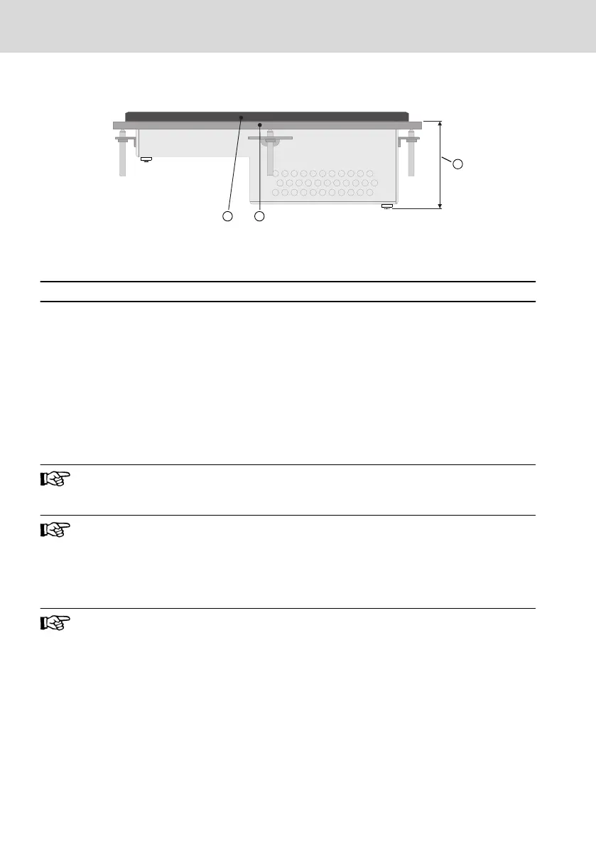
10.1.2 Overview of Housing Dimensions - Side View
① Front panel
② Mounting surface 1 to 6 mm
③ See the following table for mounting
depth
Fig. 10-2: Side view (sample illustration)
Type code Display ③Mounting depth
VR2104.01-00-01-N2-NNN-AA 4,3" 42 mm
VR2107.01-00-01-N2-NNN-AA
VR2107.01-00-01-N2-NNN-CA
7" 46.3 mm
VR2109.01-00-01-N2-NNN-AA
VR2109.01-00-01-N2-NNN-CA
9" 52.3 mm
Tab. 10-2: Mounting depth
10.2 Installation Notes
A clearance of at least 30 mm has to be complied with during the as-
sembly to ensure sufficient free air conditions.
During the horizontal mounting of the operating device, note that
heat can accumulate below the operating device due to additional
heat sources. Provide sufficient heat dissipation! Comply with the
permissible temperature range specified in the technical data for the
operation of the operating device!
To guarantee the specified degree of protection, ensure that the
seal is positioned flat on the mounting surface and that the threaded
pins of the mounting brackets are uniformly tightened. Comply with
the maximum torque of 1 Nm.
Bosch Rexroth AG
Assembly, Disassembly and Electrical Installation
VR 21
14/29
DOK-SUPPL*-VR21**.01**-IT02-EN-P

 Loading...