Loss of degree of protection IP 65!
The housing in which the operator display is installed, has to fulfil
the following conditions:
● Free from impurities
● Sufficient mechanical strength and flatness
These criteria influence the required degree of protection IP to a
great extent.
Further required measures are to be taken depending on the mount-
ing location, e. g. the stabilization of the mounting frame.
10.3 Mounting Cut-Out
The device facilitates quick and easy mounting of the rear of the device. A wall
thickness of 1 mm to 6 mm is permissible and ensure a correct assembly.
Assemble the operating device as follows:
1. Creating a mounting cut-out, see chapter 10.4 "Mounting Dimensions" on
page 16.
2. Insert the device in the mounting cut-out.
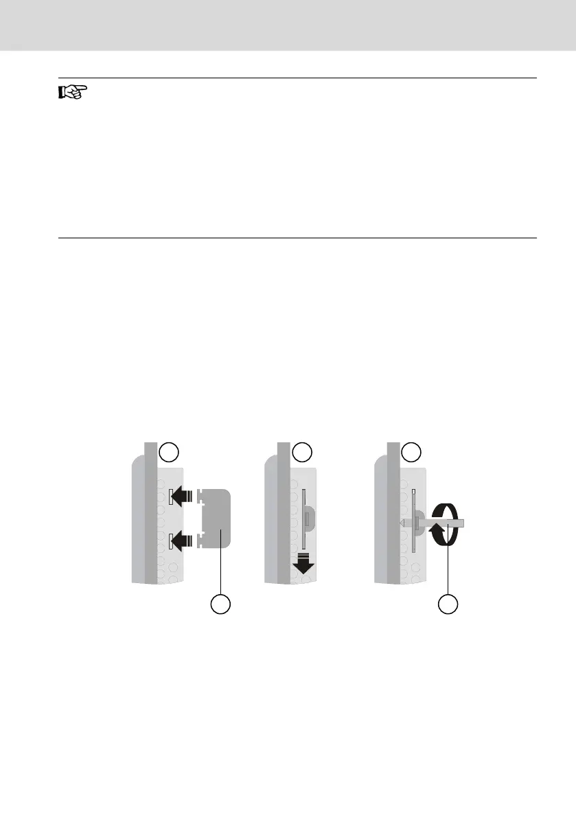
3. Position the mounting brackets in the provided cut-outs (①) and pull the
mounting brackets down until they engage (②).
4. Fix the device using threaded pins (③).
Ⓐ Mounting bracket
Ⓑ Threaded pin
Fig. 10-3: Installing the mounting brackets
VR 21 Bosch Rexroth AG
Assembly, Disassembly and Electrical Installation
DOK-SUPPL*-VR21**.01**-IT02-EN-P
15/29

 Loading...