Removing Main Components 34
2210.2657 Rev 3.0 NIPPY Clearway 2 Service Manual .
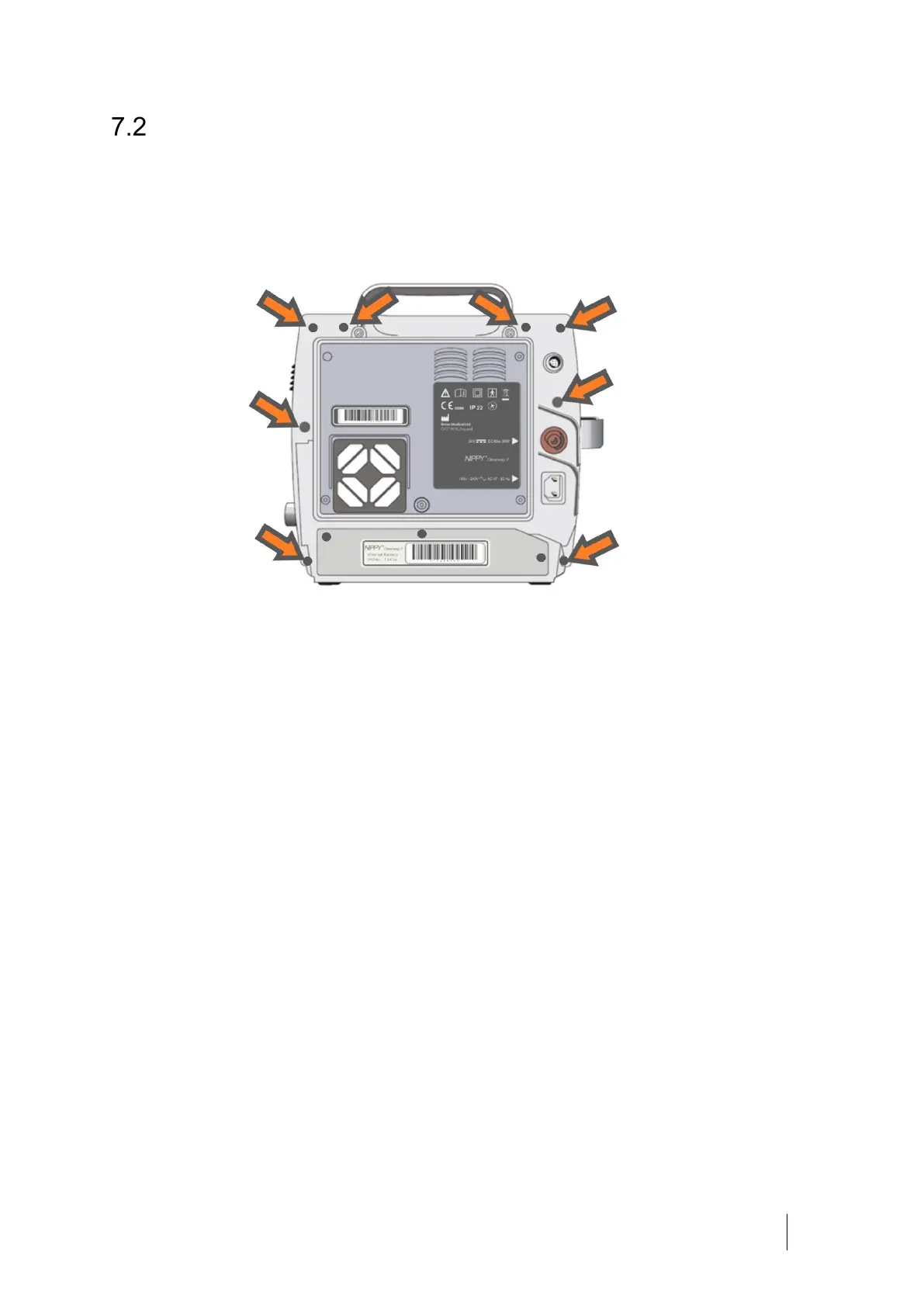
Opening and Closing the Case
Switch off the Clearway 2 and disconnect the AC mains supply.
To open the case, loosen and remove the 8 case fixing screws at the rear of
the device using a T15 x 200mm screwdriver.
With the Clearway 2 in its normal upright position carefully pull the front and
rear case halves apart. There are two cables connecting the control PCB in the
rear to the Display PCB on the front, these must now be disconnected.
Disconnect the grey ribbon cable (board interconnect) from the Control PCB,
next disconnect the power cable from the Display PCB. The two halves can
now be separated.
To close the case, ensure all components are secure and all electrical
connections have been made. Check that the two rubber ‘feet’ are fitted to the
rear case, the front case will be slid over these when fitting the case halves
together.
With the case halves in the upright position connect the power and
interconnect cables between the two PCBs, slide the front half of the case over
the two rubber feet, locating the case into the T shaped slot in the ‘foot’. Bring
the two halves of the case together ensuring the control PCB is sitting correctly
in its mountings. The two halves will fit together easily without force if all
internal components and cables are in their correct positions. When the two
halves are securely together, fit and tighten the 8 case screws.
 Loading...