Service&Troubleshooting Guide - Home Generator Systems __& Sf_an _
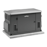
Model 1938 (I 0kW) General Information _ _'_
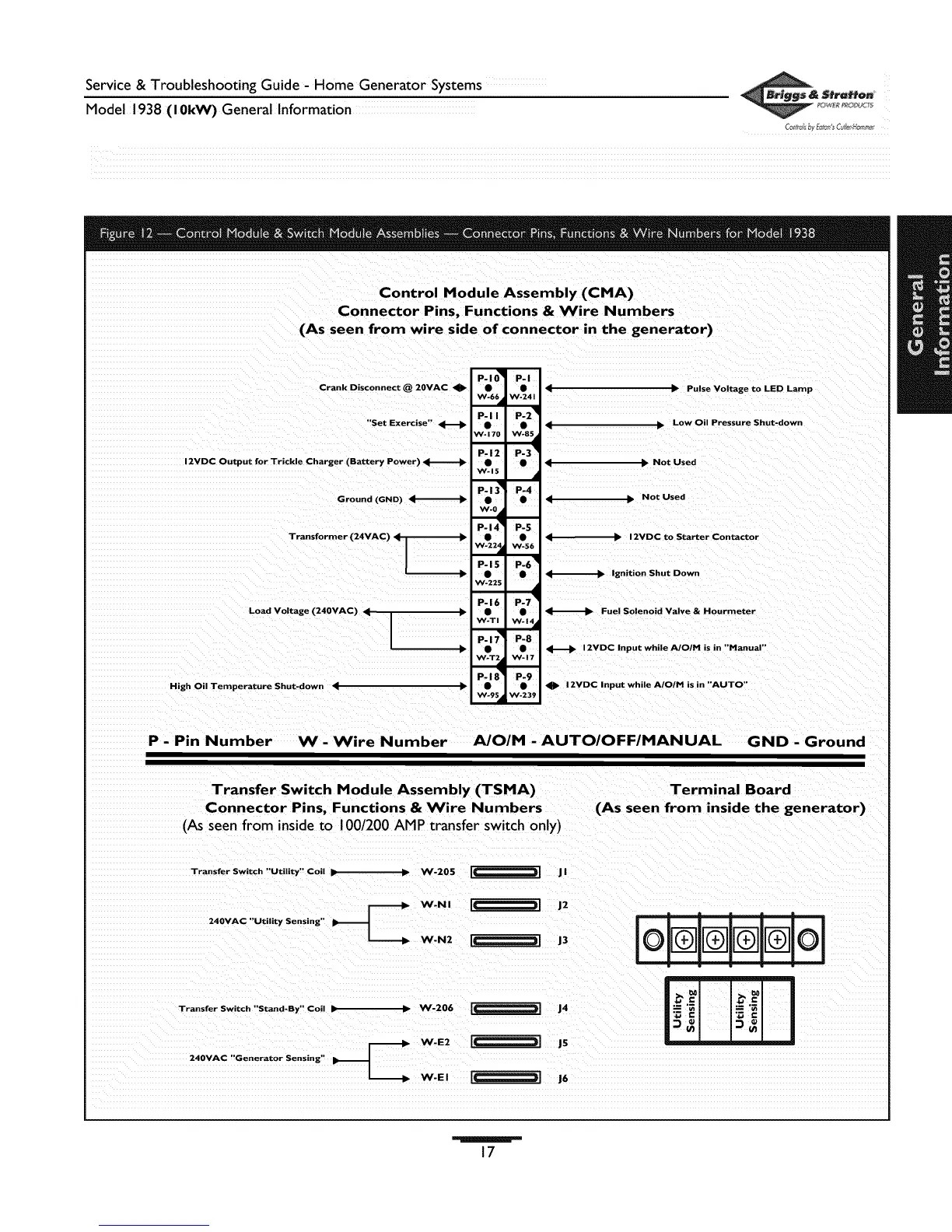
Control Module Assembly (CMA)
Connector Pins, Functions & Wire Numbers
(As seen from wire side of connector in the generator)
P-I_ P-I
Crank Disconnect @ 20VAC _1_ • • 4
W- 66al W-241
P- I I P-2 _1
"Set Exercise" H • • 4
W- 170 W-85_1
P-12 P-3 _
2VDC Output for Trickle Charger (Battery Power) _ • • 4
W-15
P-I_ P-4
Ground (GND) _ _ • •
W-0al
P. 14_1
Transformer (24VAC) _ _. •
W-22_P-15
W-225
Load Voltage (240VAC)
High Oil Temperature Shut-down q
P-16
W.TI
P.17 _
W-T_
P.18 _!
W-95al
• Pulse Voltage to LED Lamp
• Low Oil Pressure Shut-down
• Not Used
Not Used
P-5
• _ 12VDC to Starter Contactor
W-56
p.6 _1
• _ Ignition Shut Down
p.7 _
• _ Fuel Solenoid Valve & Hourmeter
W-14•
P-8
• _ 12VDC Input while A/O/M is in "Manual"
W.17
P-9
• I1_ 12VDC Input while A/O/M is in "AUTO"
W-239
P - Pin Number W - Wire Number AJO/M - AUTO/OFF/MANUAL GND - Ground
Transfer Switch Module Assembly (TSMA) Terminal Board
Connector Pins, Functions & Wire Numbers (As seen from inside the generator)
(As seen from inside to 100/200 AMP transfer switch only)
Transfer Switch "Utility" Coil _ _ W-20SL_ J I
Transfer Switch "Stand.By. Coi! _ _ W.206 I_[ J4
17
 Loading...