_& StmH__
Service &TroubleshootingGuide,HomeGeneratorSystems
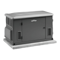
Model 1938(10kW)GeneratorAssembly
I 0kW Rotor & Stator Resistance Values
m
i oo0e. ,unit,PartNoiO.ms,
1938-0 10kW [192971GS 4.67/4.67]
[Part No,[ Power I DPE I BCW I
1192969GS1.109/.109I .30 I 0.027 I
System Interconnections
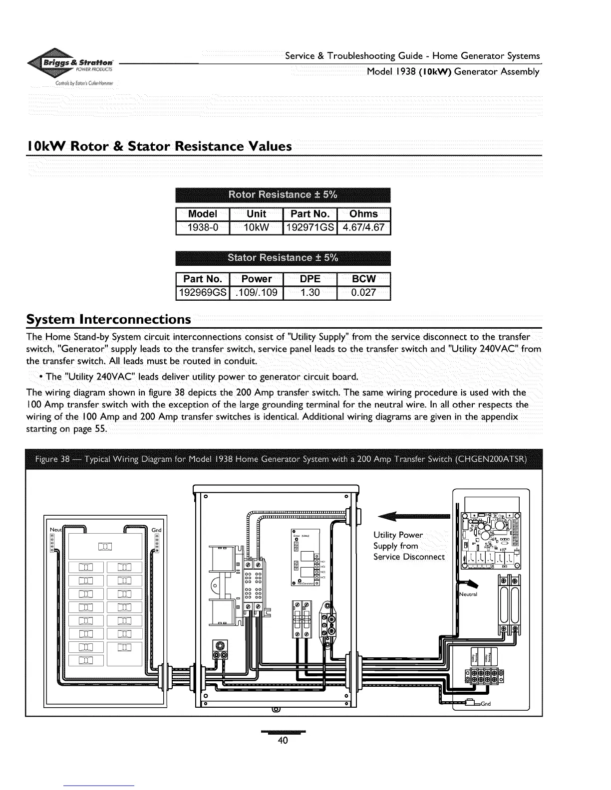
The Home Stand-by System circuit interconnections consist of "Utility Supply" from the service disconnect to the transfer
switch, "Generator" supply leads to the transfer switch, service panel leads to the transfer switch and "Utility 240VAC" from
the transfer switch. All leads must be routed in conduit.
• The "Utility 240VAC" leads deliver utility power to generator circuit board.
The wiring diagram shown in figure 38 depicts the 200 Amp transfer switch. The same wiring procedure is used with the
100 Amp transfer switch with the exception of the large grounding terminal for the neutral wire. In all other respects the
wiring of the 100 Amp and 200 Amp transfer switches is identical. Additional wiring diagrams are given in the appendix
starting on page 55.
Utility Power
40
 Loading...