~
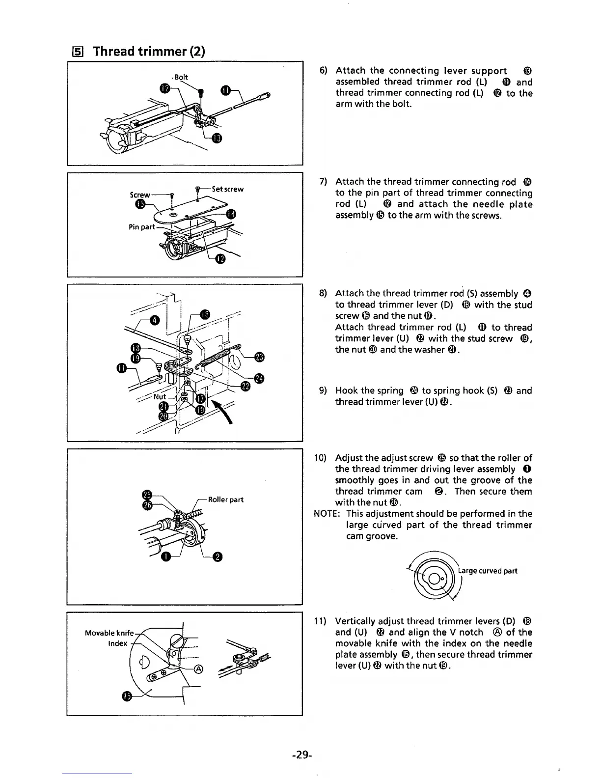
Thread trimmer (2)
.Bolt
t--Setscrew
!
-29-
6)
Attach
the
connecting
lever
support
@)
assembled thread
trimmer
rod
(L)
ID
and
thread trimmer connecting rod
(L)
0
to
the
arm
with
the bolt.
7)
Attach the thread trimmer connecting rod
4D
to
the pin part
of
thread trimmer connecting
rod
(L)
@ and
attach
the
needle
plate
assembly@
to
the arm
with
the
screws.
8)
Attach the thread trimmer rod
(S)
assembly 0
to
thread trimmer lever
(D)
@
with
the stud
screw(@
and the
nut
i).
Attach thread trimmer rod (L)
ID
to
thread
trimmer lever
(U)
0
with
the stud screw
@,
the
nut
ti9
and
the
washer
tD.
9)
Hook the spring
@to
spring hook
(S)
@)
and
thread trimmer lever
{U)
0.
10)
Adjust the adjust screw
~
so
that
the roller
of
the thread trimmer driving lever assembly 0
smoothly
goes
in and
out
the groove
of
the
thread trimmer
cam
@.
Then
secure them
with
the
nut
fD.
NOTE:
This
adjustment should
be
performed in the
large curved
part
of
the
thread
trimmer
cam
groove.
~arge
curved part
11)
Vertically adjust thread
trimmer
levers
(D)
@
and
(U)
0 and align
the
V notch ®
of
the
movable knife
with
the index on
the
needle
plate assembly
@,then
secure
thread trimmer
lever
(U)
0
with
the
nut
(ID.
 Loading...