111
Volt~ge
measurement
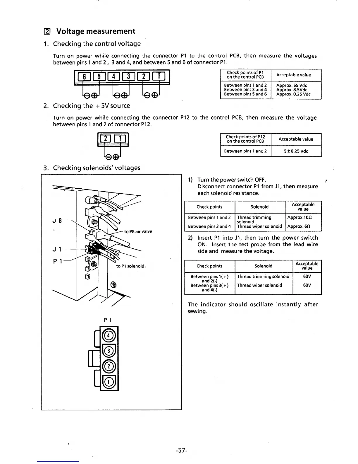
1.
Checking
the
control voltage
Turn on power while connecting the connector
P1
to
the control
PCB,
then measure
the
voltages
between pins 1 and
2,
3 and
4,
and
between 5 and 6
of
connector
P1.
Check points
of
P1
Acceptable value
on
the
control
PCB
Between pins 1 and 2
Approx.
65
Vdc
Between pins 3 and 4
Approx. 8.5Vdc
Between pins 5 and 6
Approx.
0.25 Vdc
2.
Checking
the
+
SV
source
Turn on power while connecting the connector
P12
to
the control
PCB~
then
measure
the
voltage
between pins 1 and 2
of
connector
P12.
3.
Checking solenoids' voltages
p 1
-57-
Check points
of
P12
on
the
control
PCB
Acceptable value
Between pins 1 and 2
5
±0.25
Vdc
1)
Turn the power switch
OFF.
i'·
Disconnect connector
P1
from
J1,
then measure
each
solenoid resistance.
Check points
Solenoid
Acceptable
value
Between pins 1 and 2 Thread
trimming
solenoid
Approx.100
Between pins 3 and 4 Thread
wiper
solenoid
Approx.60
2)
Insert
P1
into
J
1,
then
turn
the power switch
ON.
Insert the test probe from
the
lead
wire
side and measure the voltage.
Check points Solenoid
Acceptable
value
Between pins 1 (
+)
and 2(-)
Thread
trimming
solenoid 60V
Between pins 3(
+)
Thread
wiper
solenoid 60V
and 4(-)
The
indicator
should
oscillate
instantly
after
sewing.
 Loading...