The data and information reported in this installation manual are susceptible to change at any time and without obligation on CAME cancelli automatici s.p.a. to notify users.
Pag.
1.0 12/2007 © CAME cancelli automatici s.p.a.
ENGLISH
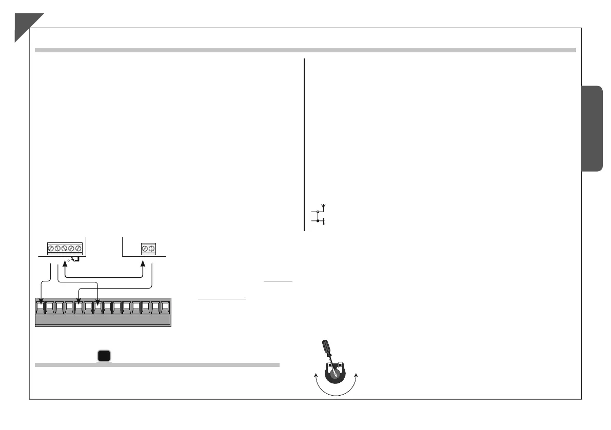
Electrical connections
Electrical connection to operate the photocells’ safety test
- Set DIP switch 8 to ON to activate the test.
IMPORTANT:
When the safety test function is activated, the N.C. contacts:
- If unused – are to be excluded on their relative DIP switches.
EN
% %
43
0
#
#
L-N
230V (a.c.) power supply
50/60 Hz
10-11
24V (A.C.) max. 30W supply accessories
10-E7
Flashing dome 24V (A.C.) max.8W
10-5
Pilot light indicating “barrier open” (24V-3W max.)
10-E6 C
ord signals 24V (A.C.) max. 24W
2-C1
Contact (N.C.) of «reopening during closing»
2-C5
Contact (N.O.) of «immediate closing»
U-V-W
230V (a.c.) motor
1-2
Stop pushbutton (N.C.)
2-3
Open pushbutton (N.O.)
2-3P Opening pushbutton (N.O.) for combined and/or bush function
2-4
Closing pushbutton (N.O.)
2-7
Command pushbutton (see dip-switch 2 in function selections)
EB-EB
Output supplied for electric lock
(VB2 = 24V electric lock, VB1 = 12V electric lock)
F-FA
Open end stop connection (N.C.)
F-FC
Close end stop connection (N.C.)
A-B-GND
Combined barrier connection
+ E D
Encoder connection
Connection of antenna
48
48
48
#
.#
(DIR)
Adjustments
C
A.C.T Trimmer = min. automatic closing time 1 sec, max. 120 sec.
The data and information reported in this installation manual are susceptible to change at any time and without obligation on CAME cancelli automatici s.p.a. to notify users.
Pag.
1.0 12/2007 © CAME cancelli automatici s.p.a.
ENGLISH
Electrical connections
Electrical connection to operate the photocells’ safety test
- Set DIP switch 8 to ON to activate the test.
IMPORTANT:
When the safety test function is activated, the N.C. contacts:
- If unused – are to be excluded on their relative DIP switches.
EN
% %
43
0
#
#
L-N
230V (a.c.) power supply
50/60 Hz
10-11
24V (A.C.) max. 30W supply accessories
10-E7
Flashing dome 24V (A.C.) max.8W
10-5
Pilot light indicating “barrier open” (24V-3W max.)
10-E6 C
ord signals 24V (A.C.) max. 24W
2-C1
Contact (N.C.) of «reopening during closing»
2-C5
Contact (N.O.) of «immediate closing»
U-V-W
230V (a.c.) motor
1-2
Stop pushbutton (N.C.)
2-3
Open pushbutton (N.O.)
2-3P Opening pushbutton (N.O.) for combined and/or bush function
2-4
Closing pushbutton (N.O.)
2-7
Command pushbutton (see dip-switch 2 in function selections)
EB-EB
Output supplied for electric lock
(VB2 = 24V electric lock, VB1 = 12V electric lock)
F-FA
Open end stop connection (N.C.)
F-FC
Close end stop connection (N.C.)
A-B-GND
Combined barrier connection
+ E D
Encoder connection
Connection of antenna
48
48
48
#
.#
(DIR)
Adjustments
C
A.C.T Trimmer = min. automatic closing time 1 sec, max. 120 sec.
 Loading...