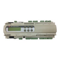
2.2 Meaning of the inputs/outputs
This table summarises the inputs and the outputs and provides a brief
description of each.
15
pCO
2
- cod. +030221835 rel. 3.0 - 18.02.03
connector signal description
J1-1 G power supply +24Vdc or 24Vac
J1-2 G0 power supply reference
J2-1 B1 universal analogue input 1 (NTC, 0/1V, 0/10V, 0/20mA, 4/20mA)
J2-2 B2 universal analogue input 2 (NTC, 0/1V, 0/10V, 0/20mA, 4/20mA)
J2-3 B3 universal analogue input 3 (NTC, 0/1V, 0/10V, 0/20mA, 4/20mA)
J2-4 GND common for analogue inputs
J2-5 +VDC power for active probes, 21Vdc (maximum current 200mA)
J3-1 B4 passive analogue input 4 (NTC, PT1000, ON/OFF)
J3-2 BC4 common analogue input 4
J3-3 B5 passive analogue input 5 (NTC, PT1000, ON/OFF)
J3-4 BC5 common analogue input 5
J4-1 VG power for optically-isolated analogue output, 24Vac/Vdc
J4-2 VG0 power for optically-isolated analogue output, 0Vac/Vdc
J4-3 Y1 analogue output no. 1, 0/10V
J4-4 Y2 analogue output no. 2, 0/10V
J4-5 Y3 analogue output no. 3, 0/10V
J4-6 Y4 analogue output no. 4, 0/10V
J5-1 ID1 digital input no. 1, 24Vac/Vdc
J5-2 ID2 digital input no. 2, 24Vac/Vdc
J5-3 ID3 digital input no. 3, 24Vac/Vdc
J5-4 ID4 digital input no. 4, 24Vac/Vdc
J5-5 ID5 digital input no. 5, 24Vac/Vdc
J5-6 ID6 digital input no. 6, 24Vac/Vdc
J5-7 ID7 digital input no. 7, 24Vac/Vdc
J5-8 ID8 digital input no. 8, 24Vac/Vdc
J5-9 IDC1 common for digital inputs 1 to 8 (negative pole if the group is DC powered)
J6-1 B6 universal analogue input 6 (NTC, 0/1V, 0/10V, 0/20mA, 4/20mA)
J6-2 B7 universal analogue input 7 (NTC, 0/1V, 0/10V, 0/20mA, 4/20mA)
J6-3 B8 universal analogue input 8 (NTC, 0/1V, 0/10V, 0/20mA, 4/20mA)
J6-4 GND common for analogue inputs
J7-1 ID9 digital input no. 9, 24Vac/Vdc
J7-2 ID10 digital input no.10, 24Vac/Vdc
J7-3 ID11 digital input no.11, 24Vac/Vdc
J7-4 ID12 digital input no.12, 24Vac/Vdc
J7-5 IDC9 common for digital inputs 9 to 12 (negative pole if the group is DC powered)
J8-1 ID13H digital input 13, 230Vac
J8-2 ID13 digital input 13, 24Vac/Vdc
J8-3 IDC13 common for digital inputs 13 and 14 (negative pole if the group is DC powered)
J8-4 ID14 digital input 14, 24Vac/Vdc
J8-5 ID14H digital input 14, 230Vac
J9 8-way telephone connector for connection to a synoptic terminal
J10 6-way telephone connector for connection to standard user terminal
J11-1 TX- RX-/TX- connector for RS485 connection to the pLAN network
J11-2 TX+ RX+/TX+ connector for RS485 connection to the pLAN network
J11-3 GND GND connector for RS485 connection to the pLAN network
J12-1 C1 common relay: 1, 2, 3
J12-2 NO1 normally-open contact relay no. 1
J12-3 NO2 normally-open contact relay no. 2
J12-4 NO3 normally-open contact relay no. 3
J12-5 C1 common relay: 1, 2, 3
J13-1 C4 common relay: 4, 5, 6
J13-2 NO4 normally-open contact relay no. 4
J13-3 NO5 normally-open contact relay no. 5
J13-4 NO6 normally-open contact relay no. 6
J13-5 C4 common relay: 4, 5, 6
J14-1 C7 common relay no. 7
J14-2 NO7 normally-open contact relay no. 7
J14-3 C7 common relay no. 7
J15-1 NO8 normally-open contact relay no. 8
J15-2 C8 common relay no. 8
J15-3 NC8 normally-closed contact relay no. 8

 Loading...