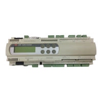
La Fig. 5.5.2.2 rappresenta il derivatore TCONN6J000, utilizzato in
coppia per la remotazione del pCO
2
in rete pLAN con cavo schermato
AWG24.
cavo AWG24 (con alimentazione)
morsetto funzione collegamenti
cavo
0terra schermo
1 +VRL primo
(≈30 Vdc) doppino A
2GND secondo doppino A
3Rx/Tx- terzo doppino A
4Rx/Tx+ terzo doppino B
5GND secondo doppino B
6 +VRL primo
(≈30 Vdc) doppino B
Tab. 5.5.2.1
5.5.3 Remotazione terminale fino a 500 m con rete pLAN con cavo
schermato AWG20/22
Tale remotazione è rappresentata in Fig. 5.5.3.1. Essa prevede
l’alimentazione indipendente del terminale condiviso.
5.6 Caratteristiche tecniche rete pLAN
Le caratteristiche tecniche della rete pLAN si possono riassumere nella
seguente tabella.
descrizione caratteristica
standard comunicazione RS485
baud-rate (kbit/s) 65,2
protocollo Multimaster (protocollo di
proprietà Carel)
lunghezza massima della rete (m) 500
Fig. 5.5.2.2 shows the TCONN6J000 connector, used in a pair for the
remote-installation of the pCO
2
in a pLAN network using an AWG24
shielded cable.
AWG24 cable (with power supply)
terminal function cable
connections
0ground shield
1 +VRL first
(≈30Vdc) pair A
2GND second pair A
3Rx/Tx- third pair A
4Rx/Tx+ third pair B
5GND second pair B
6 +VRL first
(≈30Vdc) pair B
Tab. 5.5.2.1
5.5.3 Remote installation of the terminal up to 500 m in a pLAN
network with AWG20/22 shielded cables.
This remote installation is shown in Fig. 5.5.3.1. Power supply is
independent from the shared terminal.
5.6 pLAN network technical specifications
The technical specifications of the pLAN network are summarised in
the following table.
description characteristics
Communication standard RS485
baud-rate (kbit/s) 65,2
Protocol Multimaster (Carel proprietary
control)
Maximum length of the network 500 metres
Tab.5.6.1
41
pCO
2
- cod. +030221835 rel. 3.0 - 18.02.03

 Loading...