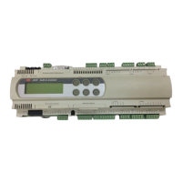
9.2.4 Uscite digitali
n. massimo 8, 13, 18, rispettivamente sulle schede: SMALL,
MEDIA, LARGE
tipo a relè elettromeccanici
Tab. 9.2.4.1
Sono raggruppate a 3 con due morsetti di polo comune per un facile
assemblaggio dei poli comuni. Prestare attenzione alla corrente
circolante nei morsetti comuni, in quanto la stessa non deve superare
la corrente nominale di un singolo morsetto (ovvero 8A). I relè sono
divisi in gruppi, a seconda della distanza di isolamento. All’interno di un
gruppo, i relè hanno tra loro isolamento principale e quindi devono
essere sottoposti alla stessa tensione (generalmente 24 Vac o 110/230
Vac).Tra i gruppi c’è il doppio isolamento quindi i gruppi possono
essere a tensione diversa.
In ogni caso verso il resto del controllo, esiste il doppio isolamento.
9.2.5 Collegamento al terminale utente
tipo asincrono half duplex a 2 fili dedicato
connet. per terminale tipo telefonico 6 vie
connettore per pLAN connettore estraibile 3 vie
driver differenziale bilanciato CMR 7 V (tipo RS485)
Tab. 9.2.5.1
Le distanze massime ammesse tra terminale e scheda base (oppure
tra i due dispositivi più lontani connessi in pLAN) sono quelle riportate
nella seguenta tabella:
9.3 Contenitore plastico pCO
2
agganciabile su guida DIN secondo Norme DIN 43880 e secondo
Norme EN 50022
materiale: tecnopolimero
autoestinguenza V0 (secondo UL94) e 960 °C (secondo IEC 695)
prova biglia: 125 °C
resistenza alle correnti striscianti: ≥ 250 V
colore: grigio RAL7035
feritoie di raffreddamento
Tab. 9.3.1
9.2.4 Digital outputs
maximum no. 8, 13, 18, respectively on the SMALL, MEDIA,
LARGE boards
type electromechanical relay
Tab. 9.2.4.1
These are divided into 3 groups with two common pole terminals to
simplify assembly of the common pole. Pay attention to the current
running through the common terminals, in that this must not exceed the
rated current of a single terminal (that is 8A).
The relays are divided in groups, depending on the insulating distance.
Inside one group, the relays have main insulation among them and
thus they must support the same voltage (generally 24Vac or
110/230Vac). Among the groups there is double insulation and so the
groups may be at different voltage.
Anyway the double-insulation does exist toward the rest of the controller.
9.2.5 Connection to the user terminal
type asynchronous half duplex with 2 dedicated
leads
connector for teminal 6-way telephone-type
connector for pLAN 3-way plug-in connector
driver balanced differential CMR 7 V (RS485 type)
Tab. 8.2.5.1
Max. allowable terminal unit-main board distances (or between the two
most far devices connected in pLAN) are listed below:
9.3 pCO
2
plastic case
click-on to DIN rail according to DIN 43880 and EN 50022 standards
material: techno-polymer
self-extinguishing V0 (according to UL94) and 960°C (according to IEC
695)
marble test: 125°C
resistance to creeping currents: ≥ 250V
colour: grey RAL7035
cooling vent
Table 9.3.1
53
pCO
2
- cod. +030221835 rel. 3.0 - 18.02.03
groups 1, 2, 3, 4, 5, 6, 7 - 8 (alarm relay) - 9, 10, 11, 12, 13 – 14, 15 - 16, 17, 18
switch contacts 1, 3, 5, on SMALL, MEDIUM, LARGE boards respectively (outputs 8, 12, 13, 14, 15)
switchable power and relative electrical parameters 2000VA, 250Vac, 8A resistive, 2A FLA, 12A LRA according to UL873 (30,000 cycles)
2A resistive, 2A inductive, cos j=0.4, 2(2)A according to EN 60730-1 (100,000 cycles)
SSR outputs 1 in alternative to relay 7 (SMALL), 2 in alternative to relays 7 and 12 (MEDIUM),
3 in alternative to relays 7, 12 and 14 (LARGE)
Tab. 9.2.4.2
gruppi 1, 2, 3, 4, 5, 6, 7 - 8 (relè d'allarme) - 9, 10, 11, 12, 13 - 14, 15 - 16, 17, 18
contatti in scambio 1, 3, 5, ripettivamente sulle schede: SMALL, MEDIUM, LARGE (uscite 8, 12, 13, 14, 15)
potenza commutabile e relativi parametri elettrici 2000 VA, 250 Vac, 8 A resistivi, 2 A FLA, 12 A LRA, secondo UL873 (30.000 cicli)
2 A resistivi, 2 A induttivi, cos j=0,4, 2(2) A, secondo EN 60730-1 (100.000 cicli)
uscite a SSR 1 in alternativa al relè 7 (SMALL), 2 in alternativa al relè 7 e 12 (MEDIUM),
3 in alternativa al relè 7, 12 e 14 (LARGE)
Tab. 9.2.4.2
cavo telefonico cavo schermato AWG24
resistenza del cavo (W/m) distanza massima (m) resistenza del cavo (W/m) distanza massima (m)
≤ 0,14 600 ≤ 0,078 600
≤ 0,25 400
Tab. 9.2.5.2
telephone cable AWG24 shielded cable
cable resistance (W/m) maximum distance (m) cable resistance (W/m) maximum distance (m)
£ 0.14 600 £ 0.078 600
£ 0.25 400
Tab. 8.2.5.2

 Loading...