20
3.6 Part Load Performance Factors
To estimate part load performance of 06D/E compres-
sors, use Table 3 below. The factors can be applied to
the full load published Carlyle capacity and power data
for all refrigerants and conditions. The system designer
should ensure the conditions are within the safe operat-
ing range of the compressor.
The table below shows multiplication factors that apply
to the compressor ratings when operating with suction
cutoff unloading.
For example: You have a 6-cylinder 06E compressor
with full load capacity = 100,000 Btu/hr (29.3 kW), full
load power = 10 kW, and full load efficiency = 10
Btu/wHr (COP = 2.92). To calculate the capacity, power
and efficiency at 2/3 load (one bank unloaded) use the
factors from the table as shown.
2/3 load capacity = .67 x 100,000 Btu/Hr
= (.67 x 29.3 kW)
Btu/Hr = 67,000 Btu/Hr
= (19.63 kW)
2/3 load power = .71 x 10 kW
= 7.1 kW
2/3 load efficiency = .94 x 10.0 Btu/wHr
COP = (.94 x 2.92)
Energy Efficiency Ratio = 9.4 Btu/wHr
COP = 2.7
3.7 Location and Size of Capacity Control Head
Assembly
The capacity control head assembly cannot be installed
and will not function on the center cylinder head of any
06D or 06E 6-cylinder compressor. This unloader can-
not be installed on Carlyle’s 2-cylinder 06D models.
Capacity control heads can be installed on either side
bank of any 6-cylinder 06D or 06E compressor.
A capacity control head can be installed on either side
bank of 4-cylinder 06E compressor.
Capacity control heads will unload either side bank of
any 4-cylinder 06D compressor but installation on the
side opposite the terminal box is recommended. This
avoids possible interference between the suction and dis-
charge pressure connections on the compressor and the
unloader coil assembly.
The suction cut-off unloader assembly has a cylinder
head which is slightly larger than a plain side cylinder
head. This results in a compressor which may be
unloaded that is slightly wider (approximately 1/2” (1.3
cm) on 06D models and 3/8” (.95 cm) on 06E models)
than a compressor without unloading capability.
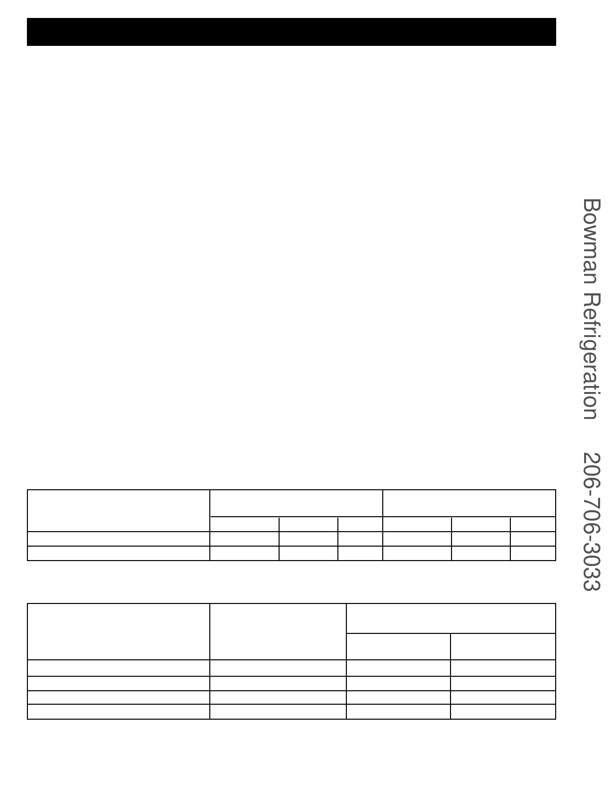
MULTIPLICATION FACTOR
FOR 1 BANK UNLOADED
ALL 4 CYLINDER MODELS
ALL 6 CYLINDER MODELS
CAPACITY POWER EER
.49 .57 .86
.67 .71 .94
COMPRESSOR MODEL
MULTIPLICATION FACTOR
FOR 2 BANK UNLOADED
CAPACITY POWER EER
---
.32 .46 .70
Table 3 – Part Load Performance Multipliers
SUCTION PRESSURE
RANGE PSI (BAR)
L.T. R-502, 404A, 507
M.T. R-502, 404A, 507
M.T. R-12, 134a
M.T. R-22 or H.T. R-22
10-25 (1.7-2.7)
30-60 (3.1-5.2)
10-30 (1.7-3.1)
30-90 (3.1-7.2)
APPLICATION
∆P REQUIRED-DISCHARGE MINUS
SUCTION PRESSURE PSI (BAR)
06D
Table 4 – Required Differential Pressure for Unloader Operation
06E
30 (2.1)
40 (2.8)
30 (2.1)
50 (3.5)
30 (2.1)
45 (3.1)
35 (2.4)
55 (3.8)
 Loading...


