22
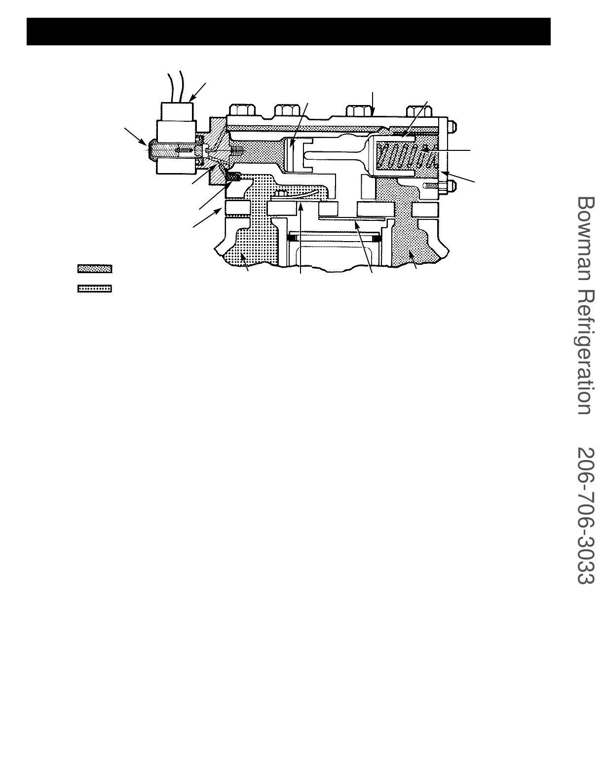
As reduced capacity is desired an external controller
energizes the solenoid coil. This opens the capacity con-
trol valve port, allowing the discharge gas behind the
unloader piston assembly to vent back to the suction
side as shown in Figure 13. The unloader valve spring at
this point can move the unloader valve body to the left,
blocking the unloader suction port. The cylinder bank is
now isolated from the compressor suction manifold,
unloading these two cylinders. No refrigerant is allowed
into the cylinders and no compression takes place.
3.10 Suction Pressure Capacity Control
Operation
Pressure-operated control valve is controlled by suction
pressure and actuated by discharge pressure. Each valve
controls 2 cylinders (1 bank). On start-up, controlled
cylinders do not load up until the differential between
suction and discharge pressures is approximately 25 psi
(1.7 bar) for 06D compressors and 35 psi (2.4 bar) for
06E models. See Table 4, page 20.
When suction pressure rises high enough to overcome
set point spring, the diaphragm snaps to the left and
relieves pressure against the poppet valve. The drive
spring moves the poppet valve to the left and it seats in
the closed position.
With the poppet valve closed, discharge gas is directed
into the unloader piston chamber and pressure builds
up against the piston. When pressure against the
unloader piston is high enough to overcome the
unloader valve spring, the piston moved the valve to the
right, opening the suction port. Suction gas can now be
drawn into the cylinders and the bank is running fully
loaded (as shown in Figure 12A).
As suction pressure drops below the set point, the con-
trol spring expands, snapping the diaphragm to the
right. This forces the poppet valve open and allows gas
from the discharge manifold to vent through the base
control valve to the suction side. Loss of full discharge
pressure against the unloaded piston allows the unloader
valve spring to move the valve left to the closed position.
The suction port is blocked, isolating the cylinder bank
from the suction manifold. The cylinder bank is now
unloaded (as shown in Figure 13A).
 Loading...


