104
30AW
Maintenance
8
N° Exchange
parts
name
Work procedure (IMPORTANT: Ensure gloves are
worn at all times to avoid risk of injury)
Remarks
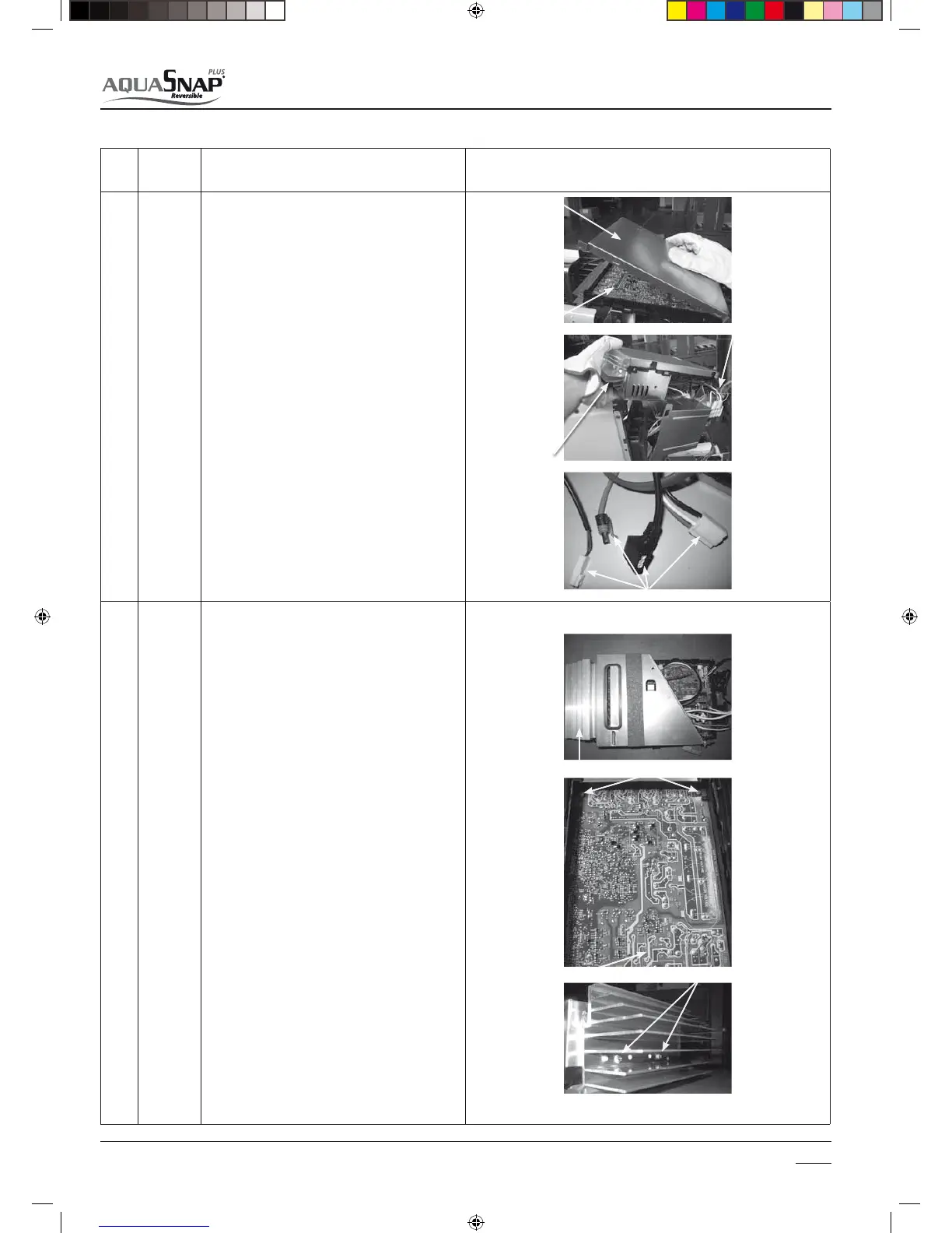
(4) Inverter
assembly
1. Perform the works from 1 to 4 of (1) and (2) .
WARNING
'PSNJOVUFBGUFSUIFQPXFSJTUVSOFEPòEPOPU
disassemble the inverter to prevent an electric shock.
Perform discharging by connecting the discharging
resistance or plug of soldering iron to + , – terminals
of the C10 too 13 electrolytic capacitor (760F) of
P.C. board.
Never use a screwdriver or similar device to di-
scharge the electrolytic capacitor components as a
electric shock may occur.
Under system fault condition, the electrolytic capa-
citor components may not have discharged. Ensure
these are discharged before proceeding.
2. Remove the inverter cover to gain access to
inspect the P.C.Board
5BLFPòTDSFXT451tQDTöYJOHUIF
main body and the inverter box.
4. Remove various lead wires from the holder at
upper part of the inverter box and wiring holder at
right side of the terminal block.
5. Remove the lead wire from the bundled part at left
side of the terminal block.
6. Pull the inverter box upward.
7. Disconnect connectors of various lead wires.
REQUIREMENT
As each connector has a lock mechanism, avoid to
remove the connector by holding the lead wire, but
by holding the connector.
(5) Control
P.C. board
assembly
t%JTDPOOFDUMFBEXJSFTBOEDPOOFDUPSTDPOOFDUFE
from the control P.C. board assembly to other parts
1. Lead wires Connection with the power terminal
block: 3 wires (Black, White, Orange) Earth wire: 1
wire (Black)
2. Connectors
Connection with compressor: Remove 3P connector.
Connection with reactor: Remove the relay connec-
tors from P08, P11 and P31,P30.CN500:
TE sensor (2P)CN501:
TD sensor (3P)
CN502: TO sensor (2P)
CN503: TS sensor (3P)
CN300: Outdoor fan (3P)
CN500: Case thermo. (2P)
CN701: 4-way valve (3P)
CN700: PMV (Pulse Motor Valve)
REQUIREMENT
As each connector has a lock mechanism, avoid to
remove the connector by holding the lead wire, but
by holding the connector.
$VUPòUJFMBQXIJDIöYFTWBSJPVTMFBEXJSFTUPUIF
inverter assembly.
5BLFPòUIFTDSFXTöYJOHUIF1$CPBSEBOEUIF
base.
5BLFPòTDSFXTöYJOHUIFIFBUTJOLBOENBJO
control board assembly side, and replace the board
with a new one.
Caution: When mounting a new board, check that
the board is correctly set in the groove of the base
holder of P.C. board base. Attach the P.C. board so
that the heat sink comes securely contact with the
metal sheet.
t.PVOUUIFJOWFSUFSBTTFNCMZ
Caution:
Mount the inverter assembly to the partition plate so
that hooks of the heat sink cover do not come near
the partition plate but also near the fan side.
t"UUBDIUIFSFNPWFEDPOOFDUPSTBUUIF1$CPBSE
BOEBUUBDIUIFUBLFOPòTDSFXTUPUIFPSJHJOBM
positions.
Inverter cover
P.C. Board
Inverter assembly
Heat sink
Dierent lock mechanisms of dierent inverter board connectors
Control P.C. board assembly
heat sink
Fixed Screws
P.C. Board
Fixed Screws
Heat sink
Terminal block

 Loading...
