103
30AW
N° Exchange
parts
name
Work procedure (IMPORTANT: Ensure gloves are
worn at all times to avoid risk of injury) Remarks
30 AWH 004, 30 AWH 006, 30 AWH 008
(1) Common
procedure
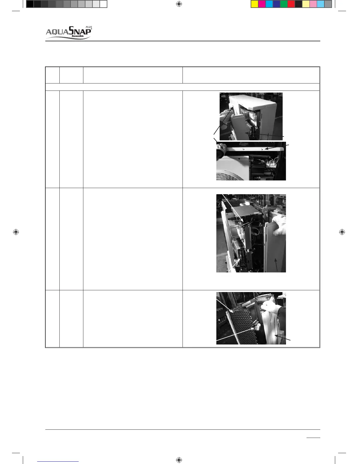
t Detachment
4UPQPQFSBUJPOPGUIFIFBUQVNQBOEUVSOPò
switch of the breaker.
3FNPWFUIFGSPOUQBOFM451tQDT
After unscrewing the screws, remove the front
panel while drawing it downward.
3. Remove the power cable from cord clamp and
terminal.
3FNPWFUIFSPPGQMBUF451tQDT
tAttachment
.PVOUUIFSPPGQMBUF451tQDT
6. Connect the power cable and to terminal, and
then x them with cord clamp.
REQUIREMENT
Secure the power cables using a tie-wrap or rub-
ber band to ensure they do not come into contact
with the compressor, valves and discharge pipe.
"UUBDIUIFGSPOUQBOFM451tQDT
(2) Side
cabinet
tDetachment
1. Perform the work from 1 to 4 of (1).
2. Remove the screws xing the inverter assembly
BOEUIFTJEFDBCJOFU.tQD
3. Remove the screws xing the GMC assembly and
UIFTJEFDBCJOFU451tQDT
4. Remove the screw for the side cabinet and the
QJQJOHQBOFM3FBS451tQD
5. Remove the screw for the side cabinet and the
CBTFQMBUF451tQDT
6. Remove the screws for the side cabinet and heat
FYDIBOHFS451tQDT
7. Remove the screws of the side cabinet and the
Brazzed plate heat exchanger assembly. (ST8P
tQDT
tAttachment
8. Replace the cabinet removed and attach the
UBLFOPòTDSFXTUPUIFPSJHJOBMQPTJUJPOT
(3) Air-outlet
cabinet
t Detachment
1. Perform the work from 1 to 4 of (1).
2. Remove the screws for the air-outlet cabinet and
UIFQBSUJUJPOQMBUF451tQDT
3. Remove the screws for the air-outlet cabinet and
UIFCBTFQMBUF451tQDT
4. Remove the screws for the air-outlet cabinet and
UIFIFBUFYDIBOHFS.tQD
t"UUBDINFOU
5. Replace the cabinet removed and attach the
UBLFOPòTDSFXTUPUIFPSJHJOBMQPTJUJPOT
Maintenance
8
8.3 Replacement of the main parts
Heat exchanger
Motor fan
Air outlet cabinet
Gloves
Front panel
Roof plate
Inverter assembly
GMC assembly
Side cabinet
SM_30AW.indd 103 14-03-2011 14:46:29

 Loading...
