18
30AW
Installation
3
Charge the water loop, with water, until the pressure on the hydro unit
reads 0.15MPa (1.5bar )
Setting NUI Code104 (installation mode) = 1 water pump is forced on.
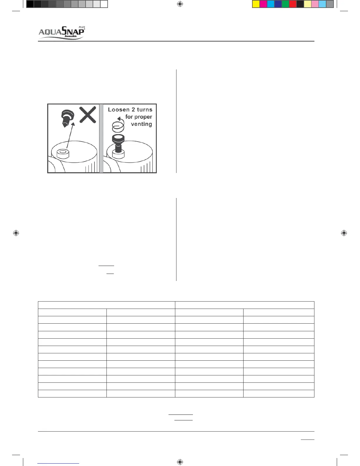
Loosen the cap of the air purge valve located on the top of back up
heater to purge air from the water circuit. If air remains in the system the
system will not operate correctly.
An expansion vessel has to be added in the water loop with 30AWH___X
and 30AWH___NX.
The capacity of the internal expansion vessel tted in 30AWH__H :
t MJUFSTGPSTJ[FTBOE
t MJUFSTGPSTJ[FBOE'PSUIJTNPEFMUIFFYQBOTJPOWFTTFM
has been dimensioned for a typical terminal fan coil water loop)
If water loop content is higher than specied in the installation manual,
an additional expansion vessel has to be added.
The expansion volume can be calculated using the following formula.
Looking for Code 111 (water ow switch status) the installer can verify if
the water ll operating is completed (when water is owing, parameter
111 = 1)
When completing the Test Run, during the commissioning of the
system, the water pressure in the system may drop below 1,5 bar. In this
event please add more water to the system.
In the case of a new installation, or cleaning the circuit, it is necessary to
perform a preventive cleaning of the system.
In order to guarantee the good operation of the product, each time you
clean the system, replace the water or add glycol, check that the liquid
appears clear, without visible impurities and that the hardness is less
than 20 °f.
3.3.8 Water loop charging, system cleaning and Water Characteristics
3.3.9 Expansion vessel (Volume calculation)
Where:
V: Necessary total vessel capacity (L)
Ⱦ 8BUFSFYQBOTJPODPFóDJFOUBUBWFSBHFIPUXBUFSUFNQFSBUVSF
Vs: Total water volume in the closed system (Do not include Hot Water
Cylinder)
P1: System pressure at tank setting position (Mpa_abs*). (Pipe inner
pressure during pump operation before heating device operates =
water supply pressure)
P2: Maximum pressure used during operation at tank setting position
(Mpa_abs*=safety valve setting pressure)
* The absolute pressure valve (abs.) is obtained by adding the atmos-
pheric pressure (0,1 MPa (1 bar)) to the gauge pressure.
The initial pressure of this expansion Vessel is 0.1Mpa (1 bar).
The release pressure of the safety valve is 0.3Mpa (3 bar).
2
1
1
P
P
Vs
V
s
E
Water temperature and expansion coecient (ε) Water temperature and expansion coecient (ε)
Hot water temperature (°C) Expansion rate (ε) Hot water temperature (°C) Expansion rate (ε)
0 0.0002 50 0.0121
4 0.0000 55 0.0145
5 0.0000 60 0.0171
10 0.0003 65 0.0198
15 0.0008 70 0.0229
20 0.0017 75 0.0258
25 0.0029 80 0.0292
30 0.0043 85 0.0324
35 0.0050 90 0.0961
40 0.0078 95 0.0967
45 0.0100 - -
Example: Maximum hot water temperature 55°C, initial water charge 0.2MPa and system volume 200 litres. The calculated Vessel capacity is:
)1.03.0(
)1.02.0(
1
2000145.0
6.11
s
SM_30AW.indd 18 14-03-2011 14:41:27

 Loading...
