19
30AW
Installation
3
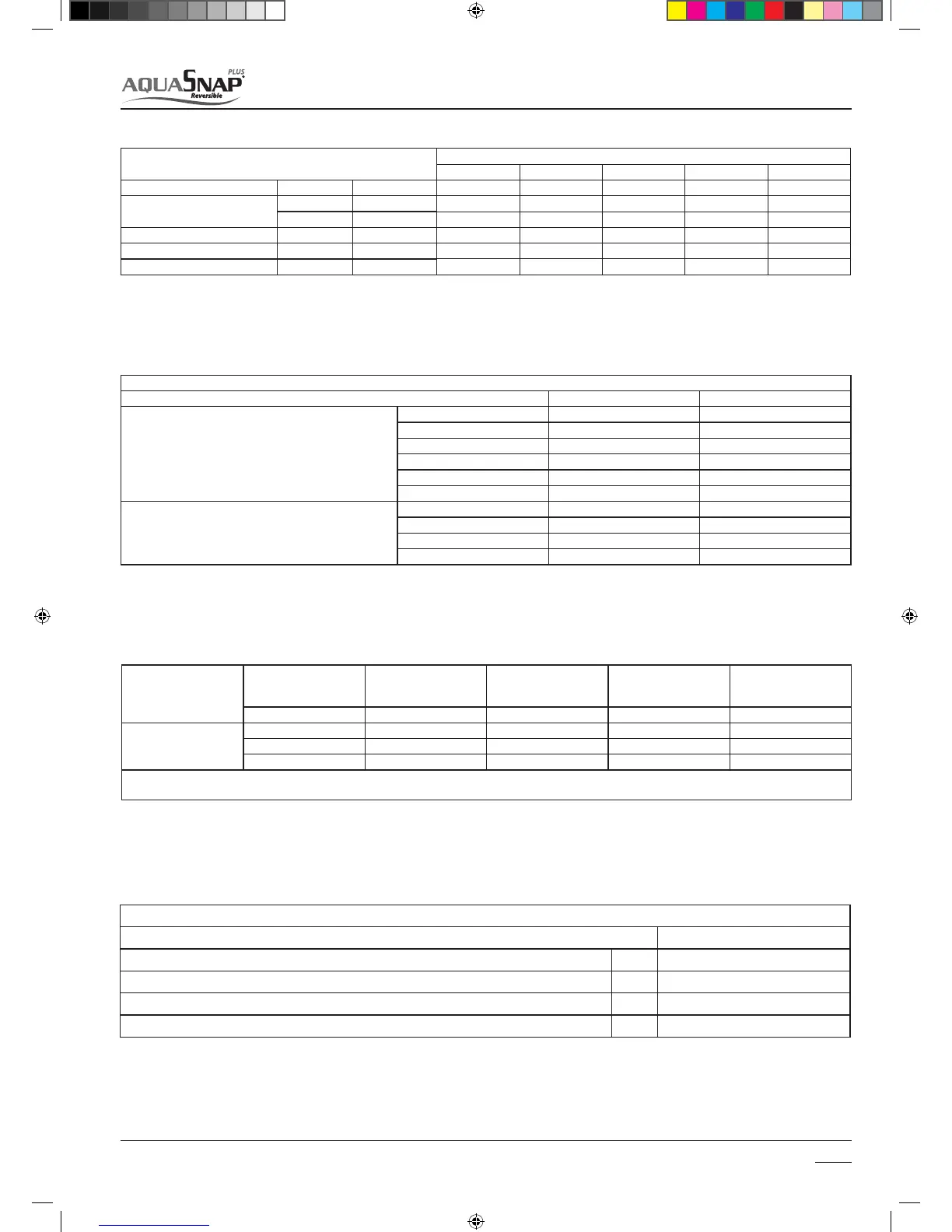
% Inhibited
Ethylene
Glycol
10% 20% 30% 40%
Freezing temperature (*) -4 °C -9 °C -15 °C -23 °C
Correction
Factors
Capacity 0,996 0,991 0,983 0,974
Absorbed power 0,990 0,978 0,964 1,008
Loss of head 1,003 1,010 1,020 1,033
(*) Note: Temperature values are indicative.
Always refer to the temperatures indicated for the specic product used
Pipe water content
Internal Diameter Outer diameter Liters / meter
copper
12 mm 14 mm 0,11 l/m
14 mm 16 mm 0,15 l/m
16 mm 18 mm 0,20 l/m
20 mm 22 mm 0,31 l/m
25 mm 28 mm 0,49 l/m
32 mm 35 mm 0,80 l/m
steel
"12.7 mm (1/2'')" 3/8'' Gas 0,13 l/m
"16.3 mm (5/8'')" 1/2'' Gas 0,21 l/m
"21.7 mm (7/8'')" 3/4'' Gas 0,37 l/m
"27.4 mm (11/16'')" 1' G as 0,59 l/m
Unit
30 AWH
004 006 008 012 015
Nominal water ow
Std l/s 0,20 0,28 0,33 0,58 0,69
Water loop content for
30AWH___H units
Min l 14 21 28 42 49
Max l 65 65 65 95 95
Max water loop pressure
Max kPa 300 300 300 300 300
Filling water pressure
Min kPa 120 120 120 120 120
Max elevation 30AW upper
Max m 20 20 20 20 20
TABLE TO USE FOR CALCULATING THE WATER CONTENT IN THE SYSTEM
Installed Unit .............
Unit content (*) l .............
Pipe content (**) l .............
Uses (fan-coil, panels, radiators, etc.) (***) l .............
Total content (****) l .............
(*) Consult the technical data table
(**) Consult the pipe water content table
(***) Consult the manual for the installed uses
(****) The water content of the system must be between the minimum and maximum values for the units with hydronic kit and greater than the minimum
value for units without hydronic kit. The minimum value is necessary to provide optimal comfort.
For units without hydronic kit, add a suitable expansion vessel to the water content of the system.
SM_30AW.indd 19 14-03-2011 14:41:27

 Loading...
