11
To CC and Y2S
4129 Extension Harness
UPM Circuit Board
Existing female plug
C
W/Y
Brown
Yellow
Gray
at valve #2
at valve #1 & 2
W/YC
END
SWIT C H
MVBR3F or MVBR4F
VALVE #1
W/YC
END
SWIT C H
MVBR3F or MVBR4F
VALVE #2
From PL5 ext. harnessFrom PL5 ext. harness
W/Y
at valve #1
Brown
Yellow
Brown
Gray
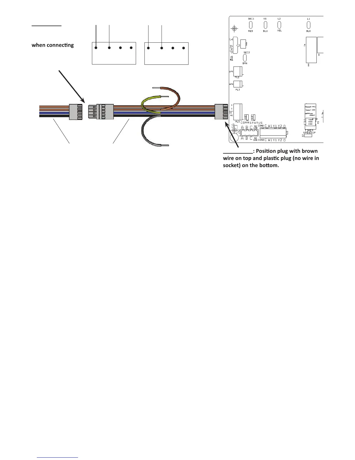
IMPORTANT:
Ensure that wire
colors match up
harness (brown
to brown, blue
to blue, black to
black.
IMPORTANT
A180276
NOTE: Y2 (connector ST1) is used for a utility curtailment input,
and is not available for use as an output for the second valve.
However, the wiring harness extension (part # 4129) used for
variable speed flow centers (closed loop applications) provides a
second stage connection as shown above (gray/brown wires). The
wiring kit should be used for systems with two solenoid valves
(yellow wire for stage 1, gray wire for stage 2, brown wire for
commontobothvalves).
Fig. 13 -- Communicating Controls -- Two Solenoid Valve
 Loading...