15
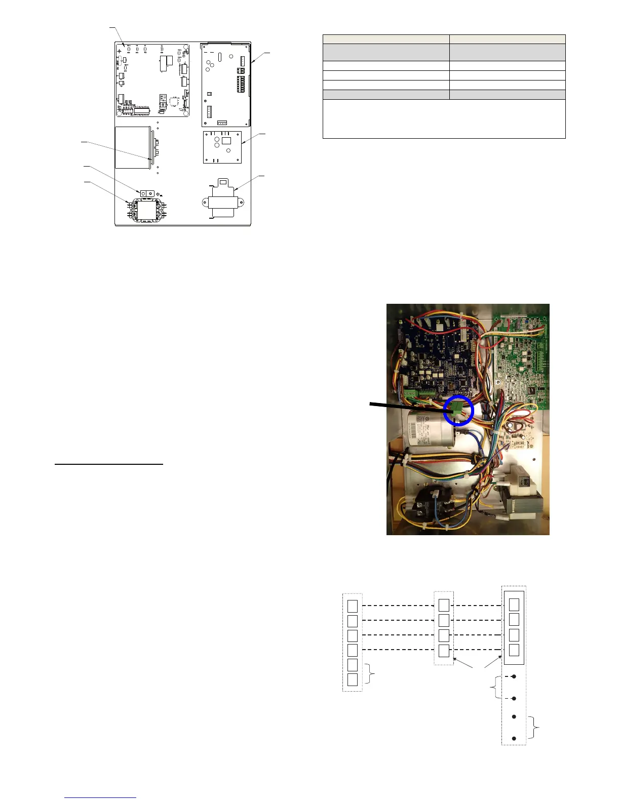
CIRCUIT BOARD
RUN
CAPACITOR
GROUNDING
LUG
CONTACTOR
2-POLE 2-THROW
TRANSFORMER
208/230 75VA
CONDENSATE
BOARD
FAN
BOARD
A150554
Fig. 16 -- Electrical Component Box Layout
ELECTRONIC THERMOSTAT
INSTALLATION
Field Connections
This section is intended as a quick reference only and should not
replace a complete review of thermostat Installation Instructions.
The GC unit can be installed as communicating with UI
communicating thermostats only.
Communicating
User Interface (UI) is designed to self-- program with the the GC
unit when connected to the unit bus com harness ABCD connector
(refer to Fig. 17) with the ABCD male adapter included with the
unit in the literature packet shipped with the unit. 4 wires are
needed as the bus com harness communicates between both unit
boards and the UI when connected.
NOTE: Field wiring only needs to go to UPM and connector as
the boards have factory wiring between them.
NOTE: It is advisable to run extra thermostat wire during
installation in the event of faulty wires, etc.
Communicating System T
ips:
SThe GC units include an Outdoor Air Temperature (OAT) sensor in
the literature packaging. Refer to Table 5 for thermostats that can
incorporate this OAT and the thermostat instructions for wiring.
SThe GC unit must be used with Wall Control version 13 or newer
software for communicating connections.
SThe Energy Tracking Kit (KHAGT0101KIT) includes a sensor and
wiring harness. The kit must be installed on the geothermal unit for
energy tracking functionality.
SWi--Fi capability will be available with the Wi--Fi Wall Controls
SYSTXCCITC01, SYSTXCCITW01, SYSTXBBECC01,
SYSTXBBECW01.
STo enter the Wall Control service mode hold the service cap in the
main menu for about 10 seconds until it turns green then release.
SThe last 10 system faults can be found in the service screens. Flash
codes on the UPM board flash only an active code with series of
short and long flashes on the amber LED. A code 37 will appear on
the UPM LED as 3 short flashes followed by a pause then 7 long
flashes followed by another pause and repeats this series. The Wall
Control will display text on the screen for the last 10 events.
SExit service screens by selecting ”Done”.
Table 5 – Recommended Thermostats
Carrier Systems: Bryant Systems:
Infinityr To u c h
Wall Control
Evolutionr Connex™
Wall Control
SYSTXCCITC01* SYSTXBBECC01*
SYSTXCCITW01* SYSTXBBECW01*
SYSTXCCITN01* SYSTXBBECN01*
* Version 13 or newer software
The GC unit is shipped with one OAT sensor in the literature package:
TSTATXXSEN01--- B
Note: Any of the model numbers above may be followed by a revision
letter such as ”---A”.
Non--Communicating (Emergency Mode Only)
Temporary Emergency Electric Heat Mode in Event of UI
Failure
In the event the system UI fails after initial UI install and there is a
need for heat while a replaceable UI can be obtained, these steps
can be followed with a non--communicating thermostat to provide
electric heat only temporarily .
The ECM board non--communicating stat connections can be
wired with a non--communicating thermostat to provide emergency
electric heat temporarily by connecting only C, W, G and R.
Disconnect the bus com harness ABCD connector to the ECM.
Do NOT wire the Y as the programming in the UPM will not allow
cooling or heating mode.
System is not to be left in this configuration for an extended
period, UI must be replaced as soon as possible.
BUS Com
ABCD Field
Connection
BUS Com
ABCD Field
Connection
A150781
Fig. 17 -- ABCD BUS COM Connection
A
B
C
D
Communicating System
Wall Control
Green - Data A
Yellow - Data B
White - COM
Red - 24VAC
Optional Remote
Room Sensor
S2
S1
ABCD
Connections
ECM
A
B
C
D
UPM
Humidifier
Connection
OAT
Sensor
(Optional)
A
B
C
D
OAT
HUM
COM
24V
White - COM
Red - 24VAC
Green - Data A
Yellow - Data B
A150168
Fig. 18 -- Universal Connection
 Loading...