16
Communicating System
Wall Control &
Smart Sensor(s)
Green
Yellow
White
Red
A
B
C
D
A B C D A B C D
Damper
Control
module
A B C D
ECM
A
B
C
D
OAT
HUM
COM
24V
Humidifier
Connection
OAT
Sensor
(Optional)
UPM
A150169
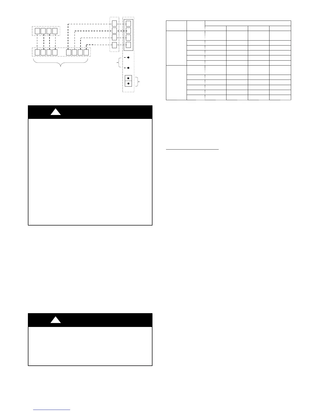
Fig. 19 -- Zoning Connection for Geothermal Package Unit
UNIT OPERATION HAZARD
Failure to follow this caution may result in improper
operation.
The electric heat lock--out feature is included because it is
required by statute for manufactured housing. This feature
must not be enabled for geothermal closed loop installations
except where required by law . When auxiliary heat is
disabled, and the GHP does not satisfy the heating call, the
GHP will continue to run, possibly non --stop for long
periods of time. Longer run times on the GHP will reduce the
loop temperature, lowering the capacity of the GHP. This in
turn causes the GHP to continue to run in an attempt to
satisfy the thermostat, which will further reduce the loop
temperature. Operating the GHP (and loop) non--stop
without the aid of auxiliary electric (when it’s needed) causes
a negative “fly--wheel” ef fect. The extreme result could be
freezing the loop fluid causing a unit lock--out which will
require switching to emergency heat while the loop recovers
(thaws).
CAUTION
!
FIELD INSTALLED COMPONENTS
Electric Heaters
Electric heater kits are available for field install options only. The
GC units can only use communicating electric heat kits. They are a
one piece, easy to install design with a wiring harness that connects
a 12-- pin connector to a 12--pin mated connector from the blower
motor harness in the motor compartment. The EH kit will slide
easily into the electric heat collar on the top of the blower housing
in all units except side discharge (due to space restrictions). In the
event of side discharge unit, external duct heaters are available.
Main power wiring to the heater is separate to the compressor
compartment. The cabinet design allows for easy cabinet access
for power cable routing via punch outs on the corner posts.
Refer to Table 6 for compatible heaters.
EQUIPMENT DAMAGE HAZARD
Failure to follow this caution may result in equipment
damage.
Failure to follow the Installation Instructions for the Electric
Heater Kits could result in equipment damage.
CAUTION
!
Table 6 – Auxiliary Electric Heaters
Heater
Series
GHP
Model
Aux. Heat Size Compatibility
5kW 10 kW 15 kW 20 kW
Internal
Mount
KWCEH
0101B05
KWCEH
0101B10
KWCEH
0101B15
KWCEH
0101B20
GC024 - -
GC036 -
GC048
GC060
GC072
External
(Duct)
Mount
KWCEH
0201F05
KWCEH
0201F10
KWCEH
0201F15
KWCEH
0201F20
GC024 - -
GC036 -
GC048 - -
GC060 - -
GC072 - -
• = Heater Kit compatible / — = Heater Kit NOT compatible
NOTES:
• Internal mount heaters used only for vertical top --- discharge and horizon-
tal end---discharge units.
• Horizontal side---discharge units require external duct heaters.
• External duct mount heaters can be used in all configurations, if desired.
IMPORTANT: 3rd party electric heaters may offer a design with
12-- pin connection but they are not recommended and may not be
recognized by the communicating controls.
Manufactured Housing
In manufactured housing applications, the Code of Federal
Regulations, Title 24, Part 3280.714 requires that supplemental
electric heat be locked out at outdoor temperatures above 40_F
(4.4_C), except for a heat pump defrost cycle.
The User Interface with an outdoor air temperature sensor can be
used to lockout supplemental heat above 40_F(4.4_C). Refer to
User Interface Setup Instructions for how to set “Electric Heat
Lockout” temperature.
To lock out the supplemental heat in the UI for systems with
electric heat:
From MAIN screen:
1. Touch “menu”
2. Touch arrow-- down
3. Touch service icon for 10 seconds until it turns green
4. Touch “setup”
5. Touch “heat source lockouts”
NOTE: Supplied outdoor air temperature sensor is field--install
option. Connect to ECM board. See Fig. 28.
Outdoor Air Temperature Sensor (OAT)
An optional outdoor air temperature (OAT) sensor is provided in
the literature package. Install the sensor outdoors, typically on the
north side of the residence away from direct sunlight. Sensor
package includes an adhesive holder for the sensor. See Fig 20 for
wiring the sensor to the OAT plug. Do not connect to the optional
remote sensor terminals (S1, S2) on the UI.
Humidity control uses the OAT to adjust humidity target when the
OAT drops into the cold range to prevent forming of condensation
on windows. It also allows the UI to display outdoor air
temperature.
 Loading...