39
Systems Communication Failure
If communication with the compressor control is lost with the
Communicating System Wall Control, the control will flash the
appropriate fault code (see Table 14) to the rest of the
communicating system, including the wall control and the indoor
geothermal unit.
Model Plug
Each control board contains a model plug. The model plug is used
to identify the type and size of unit to the control.
The correct model plug must be installed for the system to operate
properly (see Table 16).
Table 16 – Model Plug Information
Model
Number
Model Plug Num-
ber
P I N S 1 --- 4 PINS 2--- 3
GC024 HK70EZ006 5.1K 51K
GC036 HK70EZ007 5.1K 62K
GC048 HK70EZ008 5.1K 75K
GC060 HK70EZ009 5.1K 91K
GC072 HK70EZ010 5.1K 120K
On new units, the model and serial numbers are input into the
board’s memory at the factory. If a model plug is lost or missing at
initial installation, the unit will operate according to the
information input at the factory and the appropriate error code will
flash temporarily .
NOTE: RCD replacement boards contain no model and serial
information. If the factory control board fails, the model plug must
be transferred from the original board to the replacement board for
the unit to operate.
NOTE: The model plug takes priority over factory model
information input at the factory. If the model plug is removed after
initial power up, the unit will operate according to the last valid
model plug installed, and flash the appropriate fault code
temporarily.
Troubleshooting the Model Plug
If the unit is being identified incorrectly by model or size, verify
the plug resistance per Table 16. If resistance value verifies the
plug is good, ensure the plug is dry and condensate free.
NOTE: Dielectric grease (field supplied) can be used on model
plug pins if condensate has been noted after drying the plug.
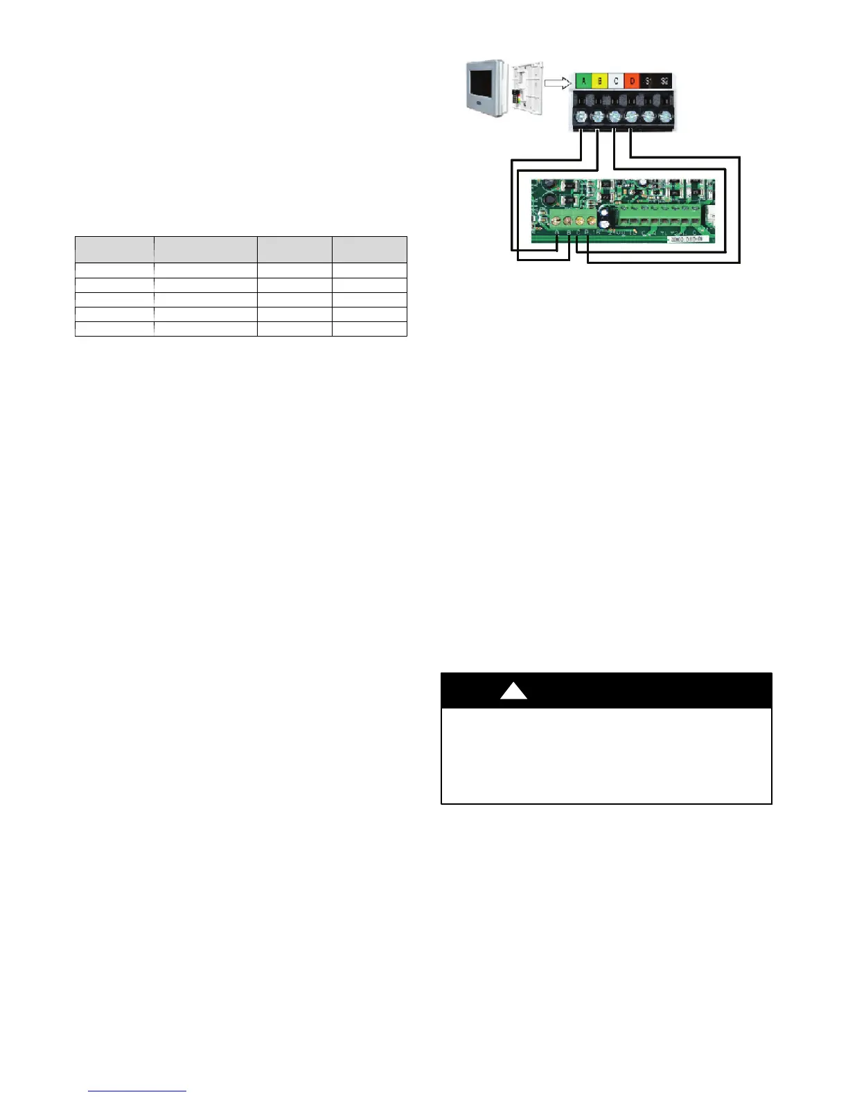
Service Tool
(A+B) Communication
(C) Common
(D) 24 Vdc
A150782
Fig. 29 -- Service Tool Connection
When working on the outdoor unit of a package system, the
technician would usually need to repeatedly walk between the
indoor wall control and the unit outside. To save time, the
communicating controls offer a service tool feature.
By wiring the service tool into the UPM board, the technician can
have a wall control capable of running the system right at the
outdoor unit.
To use a service tool, connect the A and B communication bus
wires from this second communicating control to the terminals
marked A and B on the terminal strip located in the bottom left
corner of the UPM board (see Fig. 29). But instead of connecting
the wires on the service tool to the terminals marked C and D,
connect the C and D wires from the service tool to the 24V and C
on ST1 as shown in Fig. 29.
When the service tool is connected and powered up, the
communicating controls inside the home will ”go to sleep” and let
the service tool take control of the system. In this manner, the
service technician can run the diagnostic checkouts right at the
outdoor unit using the service tool.
After the checkouts are completed and it is no longer necessary to
use the service tool, remove it from the communicating controls
and the indoor communicating controls will regain control in about
two minutes.
CAUTION
!
UNIT DAMAGE AND/OR OPERATION HAZARD
Failure to follow this caution may result in unit damage
and/or improper equipment operation.
Connect 24 across COND and COMMON on ST1
thermostat connections. Ensure condensate overflow wires
remain connected for proper protection.
 Loading...