8
Always check carefully for water leaks and repair appropriately.
Units are equipped with female pipe thread fittings. Consult Unit
Dimensional Drawings.
NOTE: Teflon tape sealer should be used when connecting water
piping connections to the units to ensure against leaks and possible
heat exchanger fouling.
NOTE: The unit is shipped with water connection O --rings. A
10-- pack of O--rings (part #4026) can be ordered through
Replacement Components (RC).
IMPORTANT: Do not over--tighten connections.
Flexible hoses should be used between the unit and the rigid
system to avoid possible vibration. Ball valves should be installed
in the supply and return lines for unit isolation. A flow regulator
should be used to set flow rate. Ball valves, flow regulator and
water solenoid valve for open loop / well water systems only.
CAUTION
!
EQUIPMENT DAMAGE AND/OR UNIT
OPERATION HAZARD
Failure to follow this caution may result in equipment
damage and/or improper operation.
Do not apply additional controlled devices to the control
circuit power supply without consulting the factory.
Doing so may void equipment warranties.
PIPING AND PLUMBING INSTALLATION
Loop Pump Connections
Flow centers using variable speed loop pumps are recommended
with these units. Variable speed pumps are more efficient and
reduce operating costs, provide full advantages of water flow rate,
temperature and display HE/HR.
When using variable speed flow centers with GC units, a special
wiring kit (part number 4129) is required.
Refer to the Flow Center installation manual for piping and wiring
instructions.
For applications using 2 GHPs and 1 flow center , refer to Table 2.
Table 2 – Requirements for Two Units Sharing One
Flow Center
Flow Center
Ty p e
Pump Sharing
Relay
Required
Wiring Kit
Required
for GC
Unit
Mode Operation
Single Speed
Flow Centers
ACPSRN (1*) 3977
Activates pump
when either GHP
calls
Variable Speed
Flow Center
(flow and tem-
perature version
required)
2 Double Pole /
Double Throw
(DPDT) Relays
(field supplied)
(2) 4129
If one unit calls,
the controller will
provide 1st stage
flow rate (set at
controller menu).
If both units call,
the controller will
provide 2nd
stage flow rate.
* 3977 wiring kit (1) is shipped with flow center (use for 1st unit). An
additional kit is needed for 2nd heat pump.
Water Solenoid Valves
Open loop well water applications require a water solenoid valve.
The purpose of the valve is to allow water to flow through the
GHP only during operation.
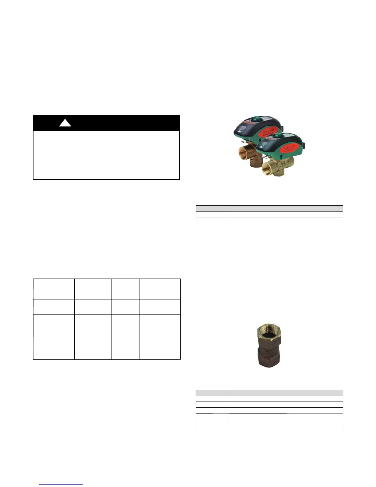
For ground water/open loop installations, solenoid valves
MVBR3F and MVBR4F are recommended due to its fast
opening/slow closing timing feature (see Fig. 6). This valve will
open in approximately 5 seconds. Solenoid valves that are slow
opening are not recommended as water in the unit’s coax may
freeze during start--up of a heating call. A frozen coax is not
covered under warranty. MVBR3 and MVBR4F valves are also
slow closing to eliminate potential water hammer .
Information on the MVBR3F and MVBR4F valves is shown
below.
A150629
Fig. 6 -- Solenoid Valves
Table 3 – Motorized Solenoid Valves
Part Number Description
MVBR3F Valve, motorized solenoid, forged brass ¾“ FPT, 24V
MVBR3F Valve, motorized solenoid, forged brass 1” FPT, 24V
*Start up note – The first time the water solenoid valve is
operated, it may require 30 to 45 seconds to power open. This
time is to charge an internal capacitor . After the initial “power up”
the valve will open in 5 seconds. If the line voltage power has
been turned off for service of the unit, the system will go through
the same first time power up sequence.
NOTE: Refer to Fig. 10 -- 13 For solenoid valve wiring.
Flow Regulator Valve
A flow regulator valve should be used to set the flow rate through
the heat pump. The lowest entering fluid temperature (EWT)
expected should be used to determine the flow rate per ton. 1.5
GPM per ton is acceptable for 50_F(10_C) EWT or higher. 2
GPM per ton should be used if EWT is below 50_F(10_C). (See
Fig. 7 and Table 4)
A150630
Fig. 7 -- Flow Regulator
Table 4 – Flow Regulators
Part Number Flow Regulator Valves
FR2 Valve, f low regulator, 3/4” FPT x 3/4” FPT, 2 GPM
FR3 Valve, f low regulator, 3/4” FPT x 3/4” FPT, 3 GPM
FR4 Valve, f low regulator, 3/4” FPT x 3/4” FPT, 4 GPM
FR5 Valve, f low regulator, 3/4” FPT x 3/4” FPT, 5 GPM
FR6 Valve, f low regulator, 3/4” FPT x 3/4” FPT, 6 GPM
FR7 Valve, f low regulator, 3/4” FPT x 3/4” FPT, 7 GPM
 Loading...