4
Well Water Systems
IMPORTANT: Table 1 must be consulted for water quality
requirements when using open loop systems. A water sample must
be obtained and tested, with the results compared to the table.
Scaling potential should b e assessed u sing the pH/Calcium
hardness method. If the pH is <7.5 and the calcium hardness is
l<100 ppm, the potential for scaling is low. For numbers out of the
range listed, a monitoring plan must be implemented due to
probable scaling.
Other potential issues such as iron fouling, corrosion, erosion and
clogging must be considered. Careful attention to water conditions
must be exercised when considering a well water application.
Failure to perform water testing and/or applying a geothermal heat
pump to a water supply that does not fall within the accepted
quality parameters will be considered a mis--application of the unit
and resulting heat exchanger failures will not be covered under
warranty. Where a geothermal system will be used with adverse
water conditions, a suitable plate--frame heat exchanger MUST be
used to isolate the well water from the geothermal unit.
Proper testing is required to assure the well water quality is suitable
for use with water source equipment.
In conditions anticipating moderate scale formation or in brackish
water, a cupronickel heat exchanger is recommended. Copper is
adequate for ground water that is not high in mineral content.
In well water applications, water pressure must always be
maintained in the heat exchanger. This can be accomplished with a
control valve installed in the discharge line.
When using a single water well to supply both domestic water and
the heat pump, care must be taken to insure that the well can
provide sufficient flow for both.
In well water applications, a slow closing solenoid valve must be
used to prevent water hammer (hammering or stuttering sound in
the pipeline). Water Solenoid valves should be connected using kit
#4129. Water solenoid must be installed in the discharge/leaving
water line. Make sure that the VA draw of the valve does not
exceed the contact rating of the thermostat. A flow regulator valve
should be installed down stream from the water solenoid valve.
CAUTION
!
UNIT OPERATION HAZARD
Failure to follow this caution may result in equipment
damage or improper operation.
Discharge air configuration change is not possible on Heat
Pumps equipped with Electric Heat Option.
1
2
3
5
6
4
7
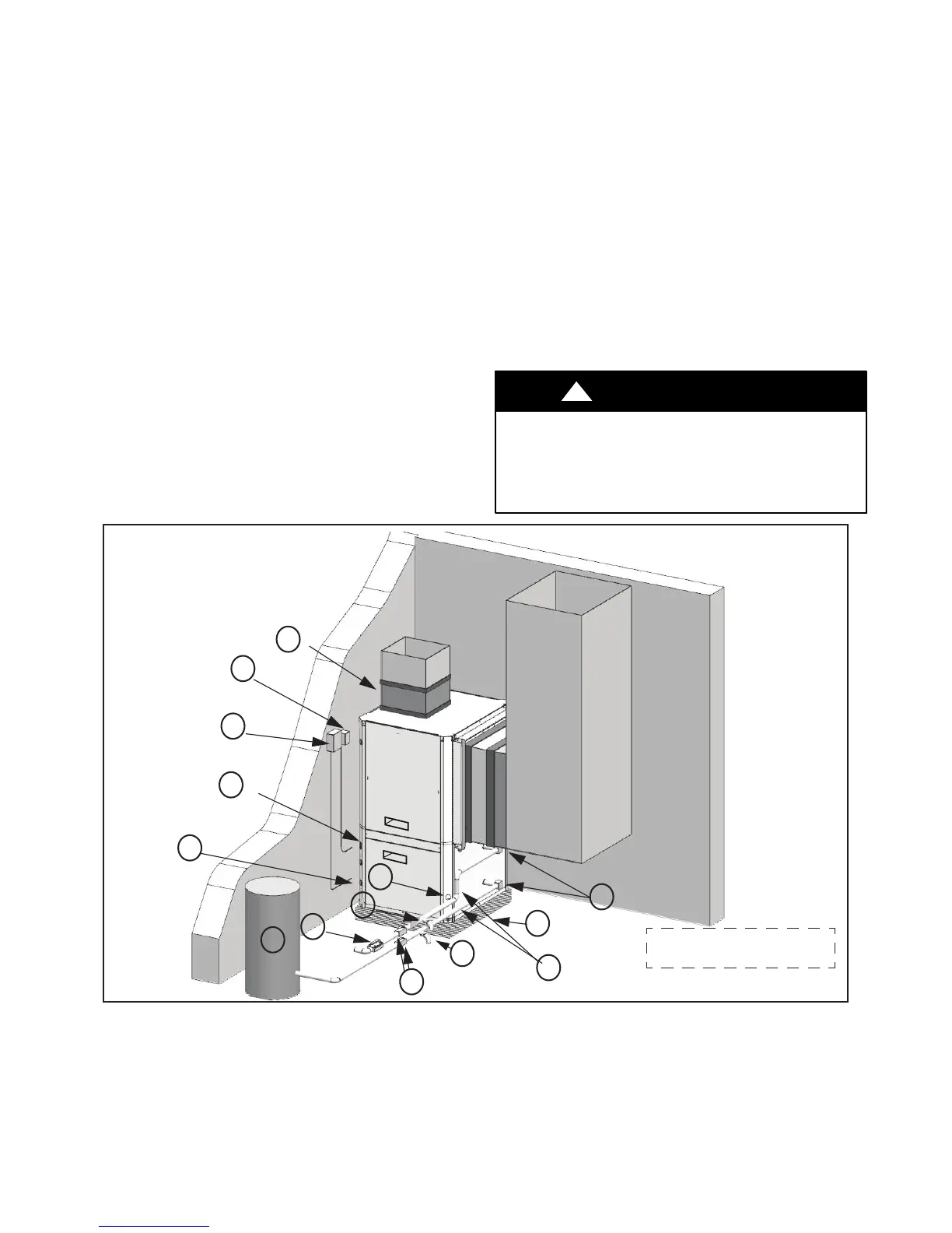
Typical Installation shown for
illustration purposes only.
9
8
10
11
12
13
14
(1) Flex Duct Connection (8) Hose Kits (optional)
(2) Low Voltage Control Connection (9) Pressure Tank (optional)
(3) Vibration Pad (10) P/T Ports (optional)
(4) Ball Valves (11) Line Voltage Connection
(5) Solenoid Valve Slow Closing (12) Electric Heater Line Voltage Disconnect
(6) Condensate Drain Connection (13) Unit Line Voltage Disconnect
(7) Drain Valves (14) Flow Regulator
A14130
Fig. 3 -- Example Well Water System Setup
 Loading...