35
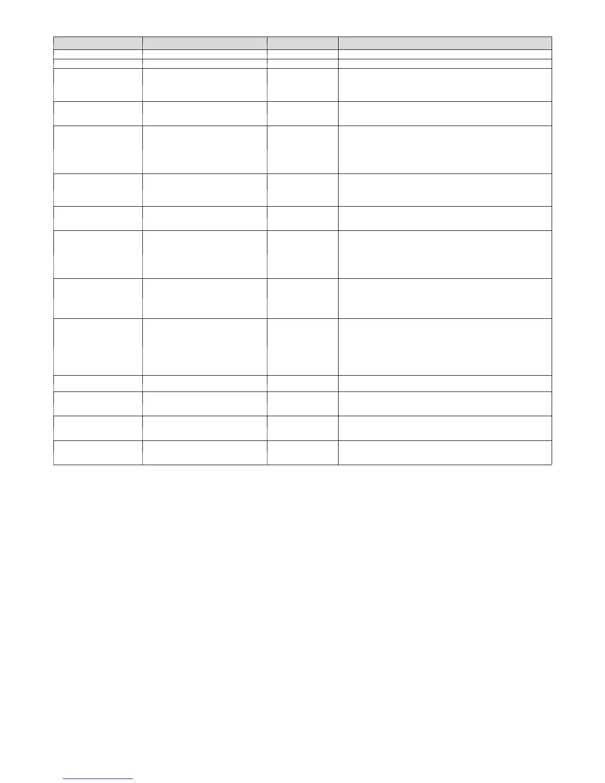
Ta ble 15 – ECM Fault Code Table
OPERATION FAULT FLASH CODE POSSIBLE CAUSE AND ACTION
Standby -- Conti nuously on
No Low Voltage or Control Failed Continuously off
System Communication Fault 16
System communications are not successful for a period exceeding
two minutes. Check system wiring to be sure the User Interface is
powered and connections are made A to A, B to B, etc. and wiring
is not shorted.
Invalid Model/Motor Selection 25
Motor size and fan coil size do not match. Motor must be replaced
with proper size motor. When a replacement ECM control is in-
stalled, enter correct model size from a list of valid sizes in UI.
Invalid Heater Size 26
No resistor is found or heater resistor value read is invalid.
- Check wiring harness connections.
- Check for a resistance value greater than 5000 ohms.
- Check for proper wiring of resistor assembly.
- Make sure heater size installed is an approved size for outdoor
unit and fan coil sizes installed.
Invalid Outdoor Unit Size 27
Outdoor unit size is invalid. Check communications wiring to be
sure User Interface has established communications with outdoor
unit or select proper size from valid size list provided at User Inter-
face.
Heater output not sensed when en-
ergized
36
ECM control energizes either heater stage and does not detect
the 24--Vac signal on output. Check for 24VAC on heater stage
outputs. Fan coil control or sensing circuit may be bad.
Heater output sensed On when not
energized
37
ECM control detects a 24--Vac signal on either heater stage out-
put and it is not supplying signal.
- Stop all system operations at User Interface and check heater
stage 24--Vac outputs.
- Disconnect electric heater at plug/receptacle 2 and check heater
wiring for faults.
Blower Motor Fault 41
Motor does not run:
- Check to be sure that the blower wheel is not rubbing the hous-
ing.
- Check motor to be sure that the motor shaft is not seized.
- Check motor windings.
Motor Communication Fault 44
Motor does not communicate with ECM control.
- Check the motor wiring harness for proper
connection to control and motor receptacles.
- Check motor wiring harness to be sure all wiring complies with
wiring diagram description
- Check 12--Vdc low--voltage supply to motor at Pins 1 (+) and 2
(--) of motor header connection to fan coil control.
Control Board Fault 45
ECM control has failed internal start--up tests and must be
replaced.
Brown Out Condition 46
The secondary voltage of the transformer falls below 15VAC for a
period exceeding four seconds. The brownout condition is cleared
when secondary voltage rises above 17VAC.
Heat Pump Temperature Sensor
Fault
52
HPT sensor is shorted or open. Check for faults in wiring connect-
ing sensor to HPT terminal. Check resistance of thermistor for a
short or open condition.
Outdoor Air Temperature Sensor
Fault
53
OAT sensor is shorted or open. Check for faults in wiring connect-
ing sensor to OAT terminal. Check resistance of thermistor for a
short or open condition.
 Loading...