— 11 —
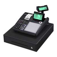
5-4. Initilize IC (Reset circuit)
VDD: Voltage of memory protection battery
To Pin No.60 of CPU
When the voltage level at Pin No.60 of CPU is not stabilized, CPU does not work properly in rare case.
Therefore, this machine uses the initialize IC for stabilizing the voltage.
Even the voltage level of VDD (Pin No.2) is changed, Pin No.1 of initilize IC outputs stabilized 5 volts.
When the VDD voltage become less than 1.9 V, the initialize IC send a reset signal to CPU.
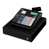
To Pin No.64 of CPU
When the VP voltage become less than 4.8 V, the pin No.1 of IC5 become “Low” level.
Then,the transistor Q44 become OFF.
When Q44 become OFF, the voltage lebel of pin No.64 of CPU changes to “High” level from “Low”. Then,
CPU knows power failure.
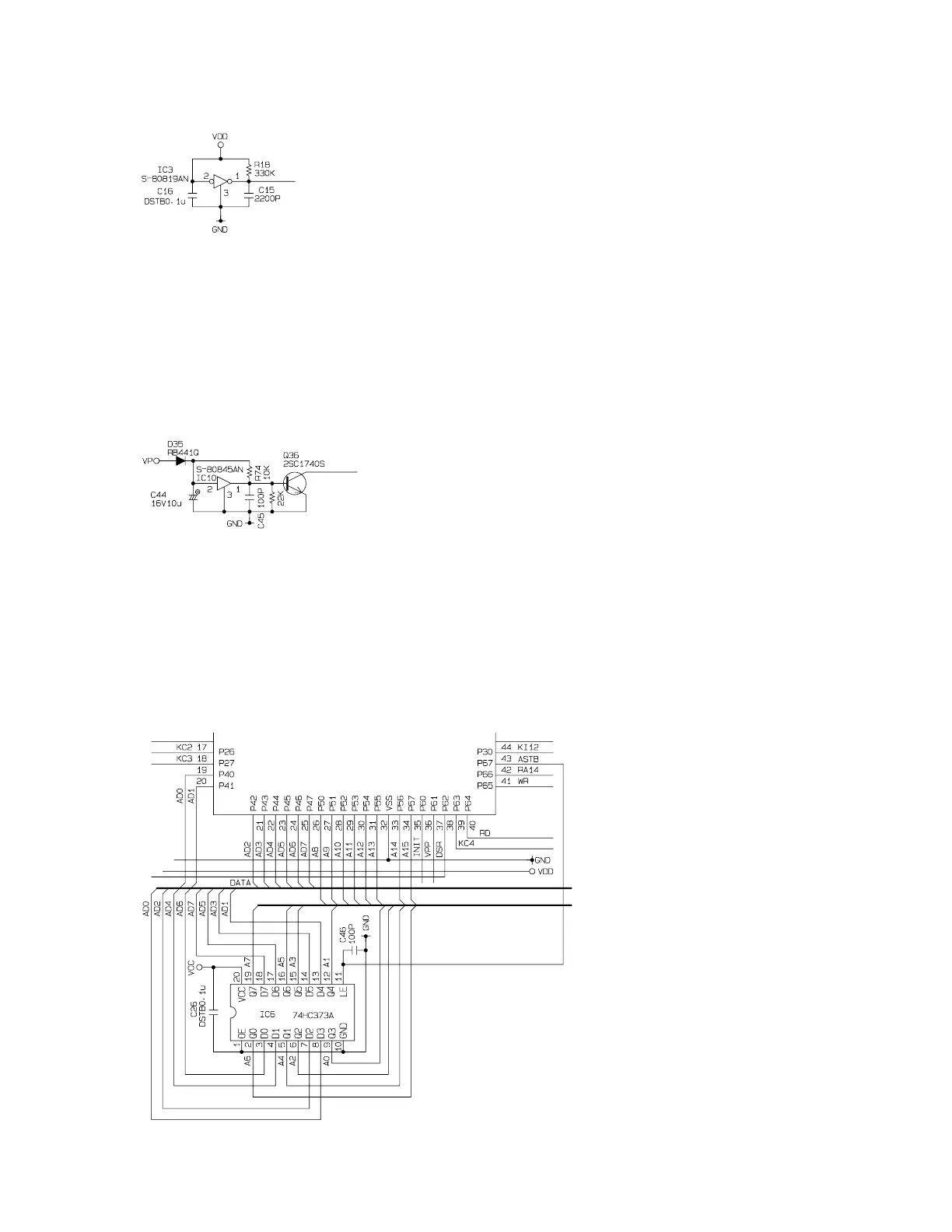
5-6. Address latch circuit
CPU uses 8 port (AD0 ~ AD7) for
address bus and data bus.
To select the address, CPU use the
IC13.
CPU send the address to IC13, and
send ASTB signal at same time.
Then, IC13 store the address and
output the address immediately.
In this way, CPU select the address
and data signal.
5-5. Power down detection circuit (PWD)

 Loading...