CONTENTS
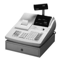
PCR365A/CE-250/CE-200 Page
1.SPECIFICATIONS........................................................................................1
2.INITIALIZE (MAC) OPERATION..................................................................2
3.BLOCK DIAGRAM.......................................................................................3
3-1.PCB CONNECTION.....................................................................................................3
3-1.BLOCK DIAGRAM.......................................................................................................4
4.DISASSEMBLY............................................................................................5
5.CIRCUIT EXPLANATION............................................................................7
5-1.Power supply circuit..................................................................................................7
5-2.CPU (uPD78052GC-159-3B9).....................................................................................8
5-3.Display controller (uPD16312GB-3B4)...................................................................10
5-4.Initilize IC (Reset circuit)..........................................................................................11
5-5.Power down detection circuit (PWD)......................................................................11
5-6.Address latch circuit................................................................................................11
5-7.RAM / ROM bank selection circuit..........................................................................12
5-8.Head drive circuit for printer...................................................................................13
5-9.Power supply circuit for display.............................................................................14
6.DIAGNOSTIC OPERATION.......................................................................15
6-1.To start the diagnostic program.............................................................................15
6-2.Check item................................................................................................................15
6-3.Operation of each test..............................................................................................15
6-4.To exit the diagnostic test.......................................................................................20
7.ERROR CODE LIST...................................................................................21
7-1.Operation error code................................................................................................21
7-2.System lock code.....................................................................................................22
8.IC DATA.....................................................................................................23
9.PCB LAYOUT............................................................................................26
10.CIRCUIT DIAGRAM...................................................................................27
11.PARTS LIST...............................................................................................42

 Loading...