– 7 –
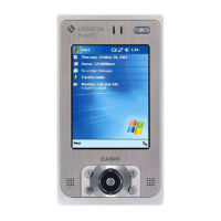
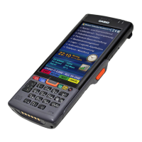
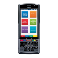
IT-G500
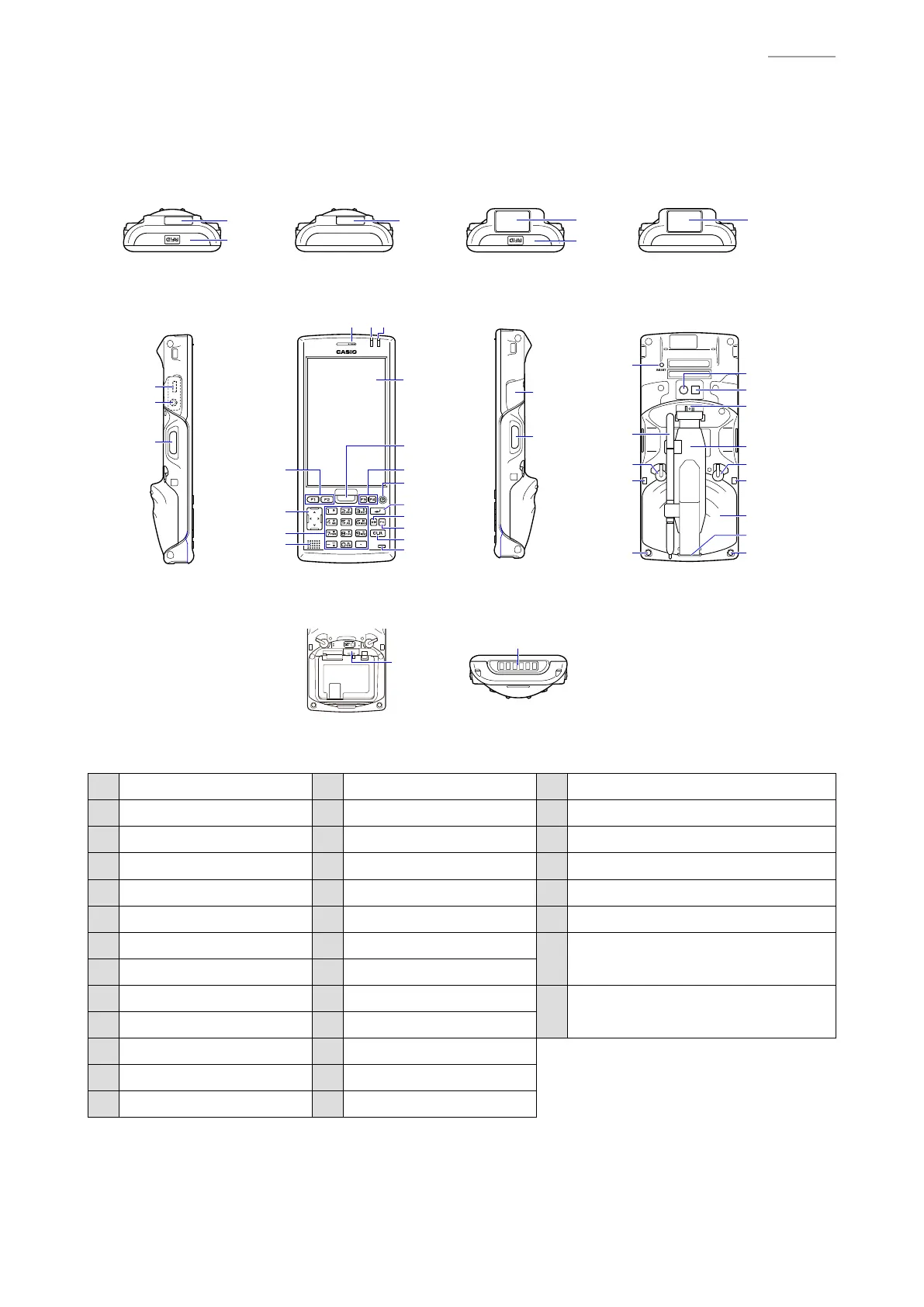
2-2. Part Names and Functions
Top
Front
(Laser Model) (CMOS Imager Model)
Right*
Battery Compartment Bottom
BackLeft*
18
19
20
12
15
14
13
11
10
4
123
5
66
7
8
9
21
22
33
34
16
17
16
16
17
16
*The illustration shows the IT-G500-C16E.
23
24
25
26
27
28
29
25
30
30
28
27
31
32
1 Receiver 14 Numeric Keys 27 Battery Pack Cover Lock Switches
2 Indicator 1 15 Cursor Key 28 Cradle Mount Holes
3 Indicator 2 16 Barcode Reader 29 Battery Pack Cover
4 Screen 17 NFC Reader 30 Strap Holes
5 Center Trigger Key 18 microUSB Port 31 Stylus
6 Function Keys 19 Headset Jack 32 Reset Switch
7 Power Key 20 L Trigger Key
33
micro SIM Card Slot for
IT-G500-GC26E/GC16E/G15E
8 Enter Key 21 microSD Card Slot
9 Mode Key 22 R Trigger Key
34
Power Supply/
Data Communication Terminals
10 Fn Key 23 Camera Lens
11 CLR Key 24 Camera Light
12 Microphone 25 Hand Belt Mount
13 Speaker 26 Hand Belt

 Loading...